PC steel rod reducing spinning device

A diameter reduction and steel rod technology, which is applied in the field of high-strength steel wire outer diameter reduction equipment, can solve problems such as manpower consumption, low slack, and physical damage, and achieve the effects of improving efficiency, avoiding injuries, and avoiding rigid transmission

Inactive Publication Date: 2017-03-29
YANSHAN UNIV
View PDF5 Cites 0 Cited by
  • Summary
  • Abstract
  • Description
  • Claims
  • Application Information

AI Technical Summary

Problems solved by technology

[0002] High-strength steel wire (PC steel rod) is a kind of prestressed steel with high technical content developed by Japan's High Frequency Thermal Refining Co., Ltd. in the 1960s. It has high strength, toughness, low relaxation, and concrete grip. Strong, good weldability, upsetting forgeability, material saving and other characteristics, has been widely used in high-strength and stress or concrete centrifugal pipe piles, electric poles, viaduct piers, railway sleepers and other prestressed components abroad; at present Rolling forging is used to process the outer circle of both ends of the steel wire. During rolling forging, the bar can only be fed in and taken out from one end of the rolling forging machine. This method requires manual feeding and processing, and workers need to take it out after processing one end. Continue to process the other end. This method consumes manpower, is inefficient, and has certain damage to the human body.

Method used


Image

  • PC steel rod reducing spinning device
  • PC steel rod reducing spinning device
  • PC steel rod reducing spinning device

Examples


Embodiment Construction

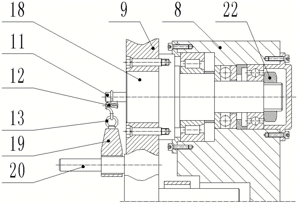
[0021] exist figure 1 and Figure 4 In the schematic diagram of the reduction spinning device for PC steel rods shown, the radial feed structure is the same structure of the two mechanisms and symmetrically arranged on both sides of the lower guide rail block 1. The hydraulic cylinder in the radial feed structure The guide rail block 2 is installed on the lower guide rail through the dovetail groove and the inclined inlay, the hydraulic cylinder front base 5 and the rear end base 3 are fixed on the hydraulic cylinder guide rail block by bolts 26, and the hydraulic cylinder 4 is fixed on the front and rear end bases.

[0022] The rotation mechanism is symmetrically arranged on the lower guide rail and connected with the radial feed structure. The wheel guide block 6 in the rotation mechanism is installed on the lower guide rail block through the dovetail groove and the oblique insert. One end of the hydraulic cylinder piston is provided with a screw thread. This end passes thr...


PUM


Abstract

A high-strength steel wire neck-spinning device comprises a lower guide rail block, a radial feeding mechanism, a rotary mechanism, an outer circle machining mechanism and a ball screw mechanism. The two sides of a steel wire are both provided with a rotary wheel and a supporting wheel of the device, when the steel wire reaches a machining position, a hydraulic cylinder piston stretches to enable the rotary wheels to move in the radial direction, and meanwhile a hydraulic cylinder of the left supporting wheel pushes the rotary wheels to move in the radial direction; when the radial mechanism moves, a motor drives a ball screw to rotate; circumferential movement of the ball screw is converted into axial movement of the guide rail block through a ball and a nut, the rotary wheel and the supporting wheel are rotated due to a motor, the radial mechanism provides rolling reduction of the rotary wheel and provides pressing force for the supporting wheel, an axial feeding mechanism provides axial displacement of a rotary wheel system, the rotary wheel squeezes the steel wire so that the steel wire can generate plastic deformation, and accordingly a steel wire outer circle is machined. By means of the device, the two ends of the steel wire can be machined at the same time, manual feeding is omitted, harm to workers caused by vibration of materials in the machining process is avoided, and steel wire machining efficiency is improved.

Description

technical field [0001] The invention relates to spinning processing equipment, in particular to high-strength steel wire outer circle diameter reducing equipment. Background technique [0002] High-strength steel wire (PC steel rod) is a kind of prestressed steel with high technical content developed by Japan's High Frequency Thermal Refining Co., Ltd. in the 1960s. It has high strength, toughness, low relaxation, and concrete grip. Strong, good weldability, upsetting forgeability, material saving and other characteristics, has been widely used in high-strength and stress or concrete centrifugal pipe piles, electric poles, viaduct piers, railway sleepers and other prestressed components abroad; at present Rolling forging is used to process the outer circle of both ends of the steel wire. During rolling forging, the bar can only be fed in and taken out from one end of the rolling forging machine. This method requires manual feeding and processing, and workers need to take it ...

Claims


Application Information

Patent Timeline
Patent Type & Authority Patents(China)
IPC IPC(8): B21D22/16
CPCB21D22/16
Inventor 卢秀春张玮刘金
Owner YANSHAN UNIV
Why Eureka
Try Eureka