
Vibrating reed, angular velocity sensor, electronic device, moving object, and method for manufacturing vibrating reed

一种角速度传感器、振动片的技术,应用在陀螺仪/转向感应设备、陀螺效应进行速度测量、速度/加速度/冲击测量等方向,能够解决电荷损失等问题,达到电荷损失抑制、提高电场效率、缩窄电极间距离的效果

Active Publication Date: 2015-05-06
SEIKO EPSON CORP
View PDF16 Cites 2 Cited by
  • Summary
  • Abstract
  • Description
  • Claims
  • Application Information

AI Technical Summary

Problems solved by technology

However, it has been clarified that, for example, when the detection part of a vibrating piece such as a gyro sensor vibrates along its thickness direction, charge loss occurs instead regardless of where the electrodes are formed.

Method used


Image

  • Vibrating reed, angular velocity sensor, electronic device, moving object, and method for manufacturing vibrating reed
  • Vibrating reed, angular velocity sensor, electronic device, moving object, and method for manufacturing vibrating reed
  • Vibrating reed, angular velocity sensor, electronic device, moving object, and method for manufacturing vibrating reed

Examples


Embodiment Construction

[0063] Hereinafter, one embodiment of the present invention will be described with reference to the drawings. In addition, the present embodiment described below does not unduly limit the content of the present invention described in the claims, and not all the configurations described in the present embodiment are necessarily essential to the solutions of the present invention.

[0064] 1. Overview of vibrator

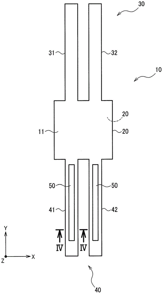
[0065] figure 1 The vibrating piece main body of the vibrating piece 10 is schematically shown in a state before electrodes are formed. Here, the vibrating piece 10 of the present embodiment has a first main surface 11 and a second main surface 12, which are aligned with each other on the X-axis (second axis) and on the plane. The X-axis and the Y-axis perpendicular to each other extend on an X-Y plane and face each other. In addition, let the axis perpendicular to the first main surface 11 and the second main surface 12 be a Z-axis. When the piezoelectric body fo...


PUM


Abstract

The vibrating reed includes a detection unit that vibrates along the thickness direction of a piezoelectric body when detecting. The detection unit includes a first main surface and a second main surface that face each other in the thickness direction, outside surfaces, a groove that has a groove bottom at a position between the first main surface and the second main surface in a depth direction from an opening provided in the first main surface, an outside surface electrode that is formed on the outside surfaces, and an inside surface electrode that is formed on an inside surface which is opposite the outside surfaces. At least one of the outside surfaces has a non-electrode-formed area where the outside surface electrode is not provided in an area from the end surface which positioned on the second main surface side in the thickness direction to the second main surface.

Description

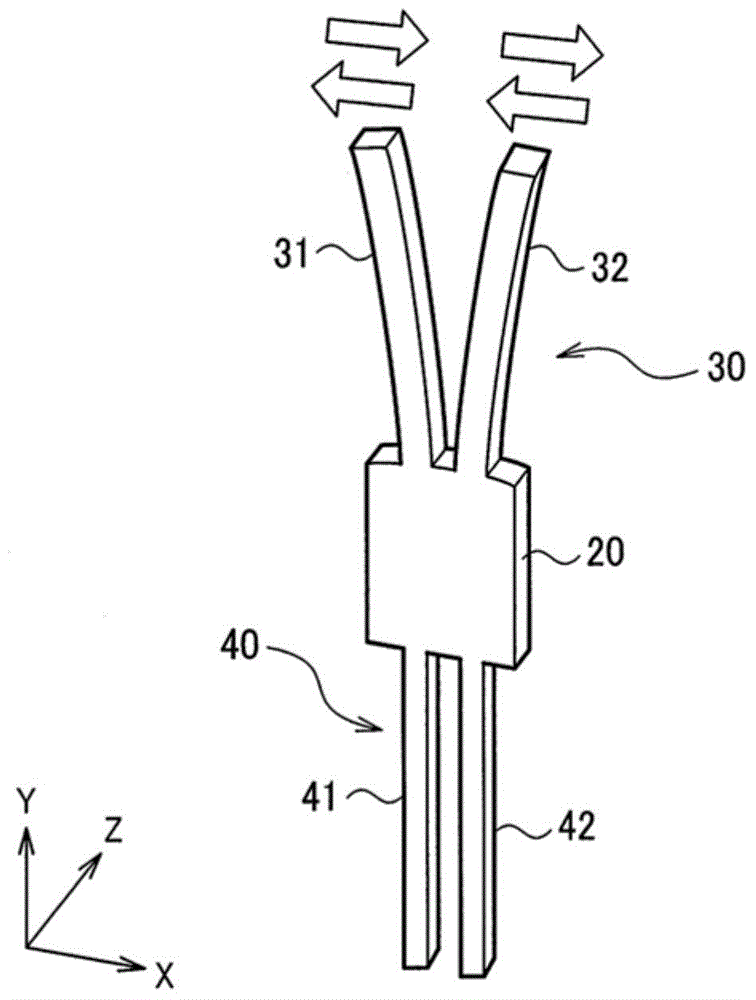
technical field [0001] The present invention relates to a vibrating piece, an angular velocity sensor, an electronic device, a manufacturing method of a moving body and a vibrating piece, and the like. Background technique [0002] In general, a vibrating piece used in an angular velocity sensor (gyro sensor) is known (Patent Documents 1 and 2). For example, in Patent Document 1 figure 1 Among them, when an angular velocity motion around the Y axis is applied to the vibrating piece extending in the Y direction, the driving part that performs in-plane vibration in the X direction in the X-Y plane will change to Z under the action of the Coriolis force Out-of-plane vibration in the axial direction (thickness direction of the vibrating element). This force component in the Z direction causes a movement of the detection part. Corresponding to this force component, an electric field in the X direction is generated in the detection unit based on the piezoelectric effect. An ou...

Claims


Application Information

Patent Timeline
Patent Type & Authority Applications(China)
IPC IPC(8): G01C19/5607G01C19/5628
CPCG01C19/5607G01C19/5628H03H9/21Y10T29/42H10N30/87
Inventor 松尾敦司
Owner SEIKO EPSON CORP
Learn More