
Split integrated underground passage steel mold plate trolley and construction method thereof

A technology of underground passages and steel formwork, which is applied in the direction of underground chambers, tunnels, tunnel linings, etc., can solve the problems of inability to realize continuous concrete pouring construction, long construction time, and difficult cleaning of side formwork, so as to achieve easy cleaning and Apply release agent, save manpower and material resources, and occupy a small area

Active Publication Date: 2015-05-06
SHANGHAI MECHANIZED CONSTR GRP
View PDF6 Cites 14 Cited by
  • Summary
  • Abstract
  • Description
  • Claims
  • Application Information

AI Technical Summary

Problems solved by technology

[0005] In view of the problems that the existing underground passage construction equipment occupies a large area, the side formwork is not easy to clean, and the construction method takes a long time, and the continuous pouring of concrete cannot be realized. The purpose of the present invention is to provide a split integrated underground passage steel The formwork trolley and its construction method, the steel formwork trolley occupies a small area and is easy to operate, which can realize continuous concrete pouring operations, improve construction efficiency, shorten the construction period, and ensure construction quality

Method used


Image

  • Split integrated underground passage steel mold plate trolley and construction method thereof
  • Split integrated underground passage steel mold plate trolley and construction method thereof
  • Split integrated underground passage steel mold plate trolley and construction method thereof

Examples


Embodiment 1

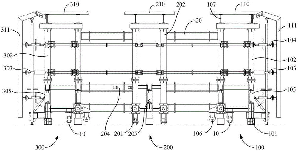
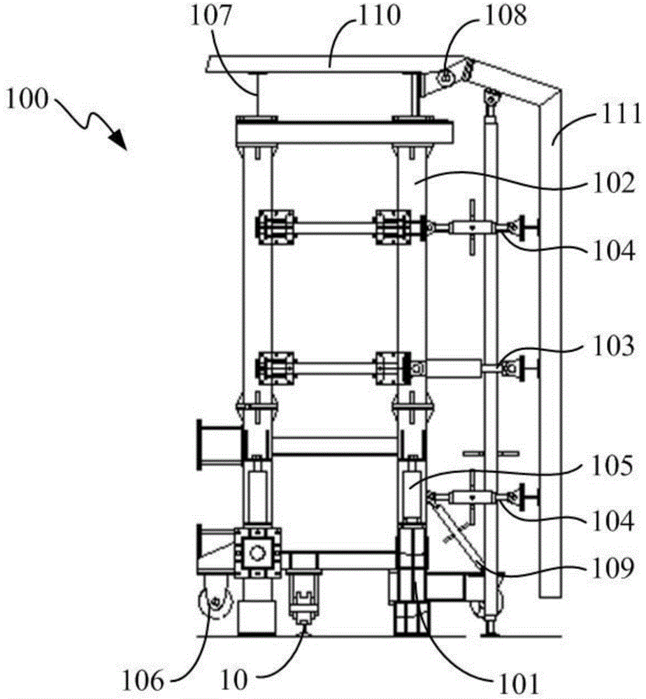
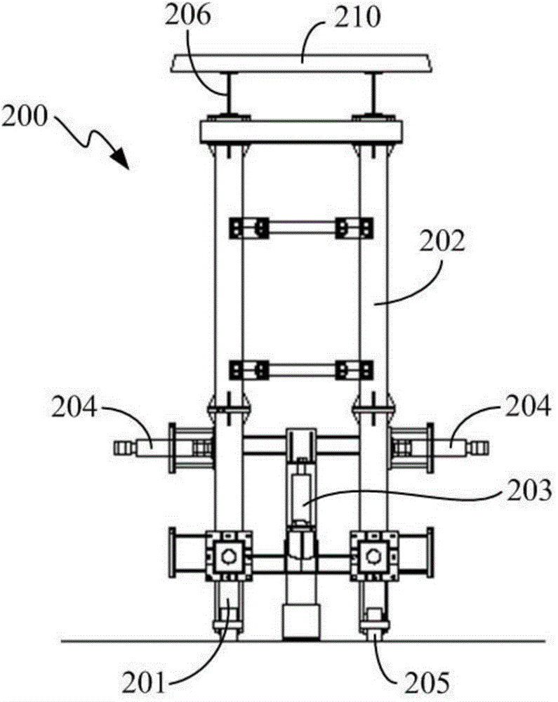
[0035] Example 1: Combining Figure 1 to Figure 8 Illustrate that the split integrated underground passage steel formwork trolley of the present invention is used to install the formwork group for pouring underground passage concrete, such as figure 1 As shown, the steel formwork trolley of this embodiment includes three frame-type formwork support devices arranged in sequence along the cross-section of the underground passage, from right to left are frame-type formwork support device one 100, frame-type formwork support device two 200 and Frame formwork support device three 300, the three frame formwork support devices (100, 200, 300) are connected as a whole through several detachable box-shaped beams 20 arranged horizontally, and frame formwork support device one 100 and frame formwork support device The bottom of formwork support device 3 300 is equipped with a running mechanism, which can drive the frame type formwork support device (100, 200, 300) to move along a pair of...

Embodiment 2

[0045] Embodiment 2: Combination Figure 8 to Figure 10 , and refer to Figure 1 to Figure 7 Illustrate the construction method of the split-integrated underpass steel formwork trolley of the present invention, and the specific steps are as follows:

[0046] Step 1: Install the formwork group on the steel formwork trolley, and arrange three frame-type formwork support devices (100, 200, 300) in sequence along the cross-section of the underground passage 50, and three frame-type formwork support devices (100, 200, 300) After arriving at the designated work position, its vertical position is connected up and down by detachable box-shaped beams 20, and it is stably and firmly located in the underground passage 50. The frame formwork support device (100, 200, 300) passes through the vertical hydraulic cylinder (105, 205, 305) are adjusted to the standard height, after the bolts are connected between two adjacent frame formwork support devices (100, 200, 300), the roof formwork su...

Embodiment 3

[0051] Example Three: Combining Figure 11 , and see Figure 1 to Figure 10 Illustrate the construction method of the split-integrated underground passage steel formwork trolley of the present invention. The difference from Embodiment 2 is that this embodiment is a pouring construction operation under the condition that the underground passage 50 has several curved arc sections, such as Figure 11 As shown, when there is a curved arc section with a radius R of 400m in the underground passage, the steel formwork trolley is decomposed into a steel formwork trolley unit 1 with a length L of 12.5m, and the box-shaped beam on the steel formwork trolley 20 is dismantled, and the three frame formwork support devices (100, 200, 300) are bolted directly into a whole, so that the width of the steel formwork trolley is narrowed, and it is convenient to move forward along the arc section of the curve in the underground passage 50. The steel formwork trolley is shortened, so that the prof...


PUM

PropertyMeasurementUnit
lengthaaaaaaaaaa
heightaaaaaaaaaa

Abstract

The invention discloses a slit integrated underground passage steel mold plate trolley and a construction method thereof, relates to the technical field of underground passage building concrete construction, and aims at the problems that the existing underground passage construction equipment is large in occupied area, the construction method is long in curing time, and continuous pouring construction cannot be realized. The steel mold plate trolley comprises at least three frame-type mold plate supporting devices which are connected integrally through detachable box-shaped cross beams, and at least two groups of posterior disassembly top mold plate supporting devices; a traveling mechanism at the lower part of the steel mold plate trolley can drive the frame-type mold plate supporting devices to move along longitudinal tracks; the two frame-type mold plate supporting devices positioned on the outer side can move in the horizontal direction under the operational control of a horizontal hydraulic oil cylinder group; each frame-type mold plate supporting device can lift in the vertical direction under the operational control of a vertical hydraulic oil cylinder group which is mounted on the corresponding frame-type mold plate supporting device; the at least two groups of posterior disassembly top mold plate supporting devices are respectively connected between the two adjacent frame-type mold plate supporting devices by bolts; universal wheels used for travelling are mounted at the bottom parts of the posterior disassembly top mold plate supporting devices.

Description

technical field [0001] The invention relates to the technical field of construction concrete construction of underground passages, in particular to a split-integrated steel formwork trolley for underground passages combined with early formwork removal technology and a construction method thereof. Background technique [0002] With the rapid development of urban construction, ground traffic congestion is increasing, and the development of underground passages is one of the effective ways to solve ground road congestion. In order to reduce the construction cost of the underground passage, some underground passages are constructed by open cut. The entire underground passage is divided into several construction units of a certain length, and the construction is gradually promoted to reduce the occupation time of the construction site and avoid hindering ground traffic. [0003] At present, the construction equipment used is a system that combines an integral formwork trolley and...

Claims


Application Information

Patent Timeline
Patent Type & Authority Applications(China)
IPC IPC(8): E21D11/10
CPCE21D11/102
Inventor 周铮黄明强周蓉峰顾逸佳叶王辉范育铭徐阿弟
Owner SHANGHAI MECHANIZED CONSTR GRP
Learn More