
Standing wave voltage protection circuit for amplifier protection

A voltage protection and circuit technology, applied in the field of standing wave voltage protection circuit, can solve the problems of increasing the chip area, complex protection circuit structure, increasing cost, etc., to achieve the effect of simple structure

Inactive Publication Date: 2015-04-29
SUZHOU INNOTION TECH
View PDF5 Cites 9 Cited by
  • Summary
  • Abstract
  • Description
  • Claims
  • Application Information

AI Technical Summary

Problems solved by technology

Most of the on-chip protection circuits detect the voltage or current of the output collector through a voltage or current detector, and use a feedback loop to clamp the voltage or current value to a certain safe value, but these protection circuits have complex structures and are not portable. Different PAs require different designs, and increase the chip area and increase the cost

Method used


Image

  • Standing wave voltage protection circuit for amplifier protection
  • Standing wave voltage protection circuit for amplifier protection
  • Standing wave voltage protection circuit for amplifier protection

Examples


Embodiment Construction

[0019] The above solution will be further described below in conjunction with specific embodiments. It should be understood that these examples are used to illustrate the present invention and not to limit the scope of the present invention. The implementation conditions used in the examples can be further adjusted according to the conditions of specific manufacturers, and the implementation conditions not indicated are usually the conditions in routine experiments.

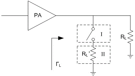
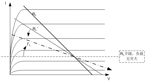
[0020] This embodiment describes a standing wave voltage protection circuit for power amplifier protection, and its principle diagram is as follows figure 1 shown, where PA is the power amplifier, R L For matched loads, R L ’ is the impedance of the discharge path, Γ L for the load R L mismatch, the mismatch impedance and R L ’ synthetic impedance.

[0021] The load matching the power amplifier is connected to the output terminal of the power amplifier, and the standing wave voltage protection circuit is co...


PUM


Abstract

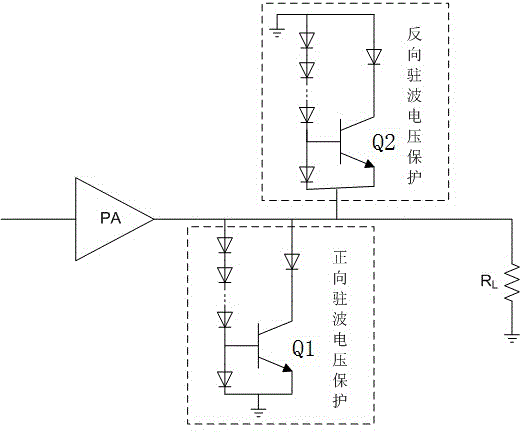
The invention discloses a standing wave voltage protection circuit for an amplifier protection, the load matched with an power amplifier is connected with the output end of the power amplifier, the standing wave voltage protection circuit is connected between the power amplifier and the load, the standing wave voltage protection circuit comprises a standing wave ratio detection circuit and a tapping passage orderly connected, one end of the standing wave ratio detection circuit is connected with the output end of the power amplifier while the other end of the standing wave ratio detection circuit is connected with the tapping passage, the other end of the tapping passage is connected to the ground. The standing wave voltage protection circuit for the amplifier protection offers the transmission passage for the radio frequency energy through the tapping passage while the load is not matched and the supplying side output is open or short-circuited and the amplifier can be protected away from burn. The standing wave voltage protection circuit for the amplifier protection has integration outside the blade, the structure is simple, and the standing wave voltage protection circuit for the amplifier protection can be conveniently connected between the power amplifier output port and the load or the antenna.

Description

technical field [0001] The invention relates to a standing wave voltage protection circuit for power amplifier protection. Background technique [0002] For power amplifiers with an output power exceeding 2W, in actual circuit applications, due to load open circuit, short circuit or mismatch, the collector port of the power amplifier output presents a relatively high standing wave distribution, so that the RF energy cannot be effectively transmitted, and most of the energy is converted It becomes heat, resulting in heat accumulation, which reduces the efficiency of the power amplifier on the one hand, and on the other hand, will cause the successful heat release to burn out. [0003] There are two methods of process improvement and circuit design in the existing power amplifier protection circuit. The improvement process is to increase the BVceo by increasing the thickness of the collector and increasing the doping of the collector, but this method will reduce the radio fre...

Claims


Application Information

Patent Timeline
Patent Type & Authority Applications(China)
IPC IPC(8): H03F1/52
Inventor 高怀田婷王锋丁杰施海健
Owner SUZHOU INNOTION TECH
Learn More