Anti-fuse structure
A technology of anti-fuse and comb structure, which is applied in the direction of electrical components, electric solid-state devices, circuits, etc., can solve the problems of harsh programming conditions, anti-fuse structure application obstacles, and difficult implementation, so as to achieve easy programming and solve long-term problems. Stability, the effect of optimizing programming conditions
- Summary
- Abstract
- Description
- Claims
- Application Information
AI Technical Summary
Problems solved by technology
Method used
Image

Examples
Embodiment approach
[0051] The inner side of the second finger-shaped metal wire is also provided with protruding ends at intervals, and the protruding ends on the first finger-shaped metal wire are opposite to the protruding ends on the second finger-shaped metal wire, or the The protruding end on the first finger-shaped metal wire and the protruding end on the second finger-shaped metal wire are alternately arranged, and the protruding end on the first finger-shaped metal wire is connected to the second finger-shaped metal wire. The gaps between the raised ends of the wires are opposite.
[0052] Further, the inner and outer sides of the first finger-shaped metal wire are provided with protruding ends at intervals along the longitudinal direction.
[0053] Further, the first comb-shaped metal part I includes two first finger-shaped metal wires, and the second comb-shaped metal part II includes two second finger-shaped metal wires, wherein the first finger-shaped metal wires Alternately arrange...
Embodiment 1
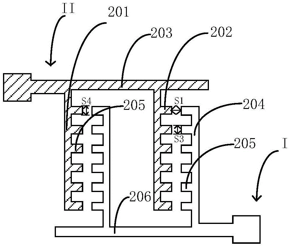
[0057] First refer to Figure 2e , the antifuse structure includes a first comb-shaped metal part I and a second comb-shaped metal part II, and the first comb-shaped metal part I and the second comb-shaped metal part II are arranged opposite to each other;
[0058] Wherein the first comb-shaped metal part I includes two first finger-shaped metal wires 204, the second comb-shaped metal part II includes two second finger-shaped metal wires 201, and the first finger-shaped metal wires 204 Alternately arranged with the second finger metal wire 201, wherein, the inner side of the first finger metal wire 204 close to the second finger metal wire 201 is provided with a raised end 205, and the raised end 205 The distance from the second finger metal line 201 is S1.
[0059] In this embodiment, the first metal finger 204 and the second metal finger 201 are divided into two groups, and each group includes a first metal finger 204 and a second metal finger 201, The distance between the...
Embodiment 2
[0071] First refer to Figure 2a , in this embodiment, the inner side of the second finger-like metal wire 201 is also provided with a raised end 205, the inner side of the second finger-like metal wire 201 refers to the protrusion near the first finger-like metal wire On one side of the starting end 205, the protruding end 205 on the first finger-shaped metal wire 204 is opposite to the protruding end 205 on the second finger-shaped metal wire 201, and the first finger-shaped metal wire 204 The distance between the protruding end 205 on the top and the protruding end 205 on the second finger metal wire 201 is S1.
[0072] The protruding ends 205 are longitudinally spaced inside the second finger-shaped metal wire 201 , and the gap between adjacent protruding ends 205 on the second finger-shaped metal wire 201 is S2.
[0073] Preferably, the protruding end 205 on the second finger metal wire 201 is a dot-shaped protruding, and the protruding is square, such as square or recta...
PUM
 Abstract
Description
Claims
Application Information
 - R&D
- Intellectual Property
- Life Sciences
- Materials
- Tech Scout
- Unparalleled Data Quality
- Higher Quality Content
- 60% Fewer Hallucinations
Browse by: Latest US Patents, China's latest patents, Technical Efficacy Thesaurus, Application Domain, Technology Topic, Popular Technical Reports.
© 2025 PatSnap. All rights reserved.Legal|Privacy policy|Modern Slavery Act Transparency Statement|Sitemap|About US| Contact US: help@patsnap.com