
Two-free-curved-surface optical lens used for ultrathin direct-lit type LED backlight system

A technology of backlight system and curved surface lens, which is applied in the field of double free-form surface optical lens, can solve problems such as difficult to meet uniform illumination, inability to accurately control the angular distribution of light intensity, dark spots, etc.

Active Publication Date: 2015-04-29
SOUTH CHINA UNIV OF TECH
View PDF4 Cites 10 Cited by
  • Summary
  • Abstract
  • Description
  • Claims
  • Application Information

AI Technical Summary

Problems solved by technology

The solution of edge-emitting LED mainly uses the property of total reflection of the medium to realize the control of light, but due to the limitation of the total reflection angle, this solution cannot accurately control the angular distribution of light intensity
At the same time, the central light intensity of edge-emitting LEDs is low, which is easy to cause dark spots, which has a great impact on the uniformity of the backlight system.
However, the light intensity of the Lambertian LED light source has a cosine distribution, the light intensity in the center is relatively large, and gradually decreases from the center to both sides, so that the illuminance formed on the target lighting surface decays rapidly with the increase of the exit angle, which is difficult to meet The need for uniform lighting

Method used


Image

  • Two-free-curved-surface optical lens used for ultrathin direct-lit type LED backlight system
  • Two-free-curved-surface optical lens used for ultrathin direct-lit type LED backlight system
  • Two-free-curved-surface optical lens used for ultrathin direct-lit type LED backlight system

Examples


Embodiment Construction

[0058] The implementation of the present invention will be described in detail below with reference to the drawings and embodiments, but the implementation of the present invention is not limited thereto.

[0059] A double free-form surface optical lens for ultra-thin direct LED backlight system, the lens is made of transparent material, the transparent material is optical glass or PMMA or PC, the lens includes two free-form surfaces, respectively constitute the incident surface and the exit surface . There is a cavity in the center of the bottom surface of the lens for installing the LED therein. The wall of the cavity is a free-form surface, which constitutes the incident surface; the outer surface of the lens is also a free-form surface, which constitutes the outgoing surface.

[0060] 1. Set the initial conditions and divide the solid angle of the LED light source.

[0061] First, the distance between the target lighting surface and the LED is 12mm, the target lighting ar...


PUM


Abstract

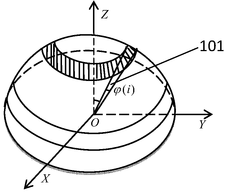
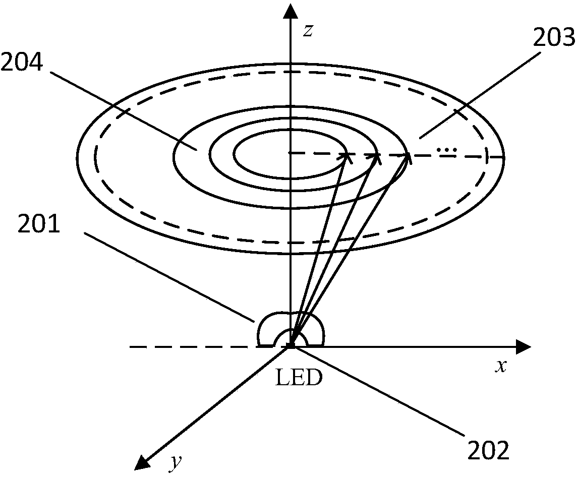
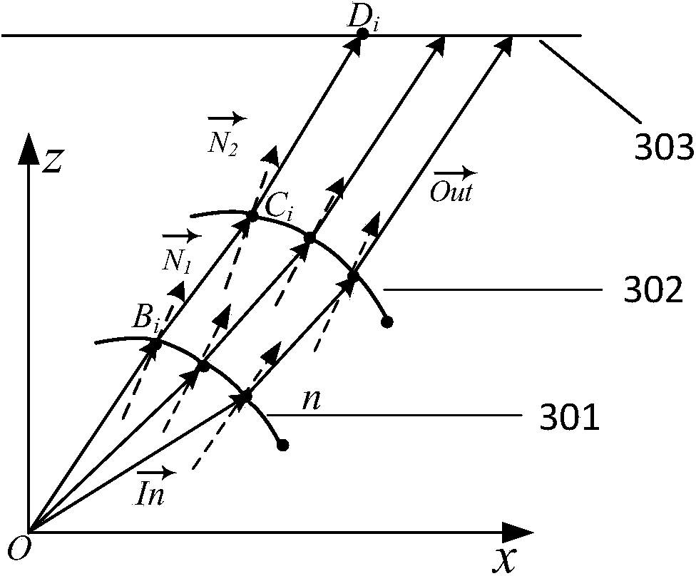
The invention provides a two-free-curved-surface optical lens used for an ultrathin direct-lit type LED backlight system. The two-free-curved-surface optical lens comprises two free curved surfaces which serve as an incidence face and an emergent face respectively. According to the shape of the free curved surface lens, a spatial right-angle coordinate system is established with an LED light source as an original point, the plane where the LED bottom face is located serves as a plane XOY, the axis passing through the original point and perpendicular to the plane XOY serves as a Z axis, the light source three-dimensional angle is divided first, annular belt division is conducted on the illumination area on the target illumination face, the mapping relation between the light source three-dimensional angle and the annular belt area on the target illumination face is established according to the law of conservation of energy, and the final double-free-curved-surface lens is obtained through the geometric relation according to the laws of refraction and reflection. The two-free-curved-surface optical lens is small in size, light rays emitted by LEDs can form circular light spots which are uniform in luminance distribution after passing through the two-free-curved-surface optical lens, and the output efficiency of the lens is quite high.

Description

technical field [0001] The invention relates to the field of LED displays, in particular to an optical lens with double free-form surfaces used in an ultra-thin direct-lit LED backlight system. Background technique [0002] In recent years, with the rapid development of liquid crystal display technology, backlight technology, which is one of the core technologies of LCD display, has also been greatly developed. As a new light source, LED will gradually replace traditional light sources and become the mainstream light source for backlight systems due to its advantages of fast response, small size, long life, excellent color temperature, strong shock resistance, energy saving and environmental protection. [0003] According to the position of the LED light source, the LED backlight system can be divided into side-lit type and direct-lit type. The edge-lit backlight system places the LED light source on the side of the specially designed light guide plate, and the number of LE...

Claims


Application Information

Patent Timeline
Patent Type & Authority Applications(China)
IPC IPC(8): F21V5/04F21Y101/02
CPCF21V5/04F21Y2101/00
Inventor 吴衡张宪民
Owner SOUTH CHINA UNIV OF TECH
Learn More