
A steel pipe quenching device

A quenching device and steel pipe technology, which is applied in the direction of quenching devices, furnaces, heat treatment equipment, etc., can solve the problems of restricting quenching quality, achieve the effects of improving quenching quality, increasing turbulence intensity, and simple structure

Inactive Publication Date: 2017-01-18
HENAN POLYTECHNIC UNIV
View PDF4 Cites 0 Cited by
  • Summary
  • Abstract
  • Description
  • Claims
  • Application Information

AI Technical Summary

Problems solved by technology

However, when the device quenches the steel pipe, there are large differences in the cooling speed of the steel pipe along the axial direction and between the inner and outer walls, which restricts the further improvement of the quenching quality.

Method used


Image

  • A steel pipe quenching device
  • A steel pipe quenching device
  • A steel pipe quenching device

Examples


Embodiment Construction

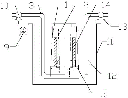
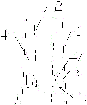
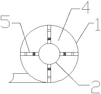
[0017] Such as figure 1 , figure 2 and image 3 As shown, a steel pipe quenching device includes a conical shrinking outer cylinder 1, a conical expanding inner cylinder 2 and a high-pressure water supply pipeline 3. The conical shrinking outer cylinder 1 is a frustum-shaped cylinder with a small upper end and a larger lower end. The inner cylinder 2 is a truncated cone-shaped cylinder with a large upper end and a smaller lower end. The conical expanding inner cylinder 2 is fixedly arranged in the conical shrinking outer cylinder 1, and the conical expanding inner cylinder 2 and the conical shrinking outer cylinder 1 are arranged coaxially. The outer surface of the tapered expansion inner cylinder 2 and the inner surface of the conical contraction outer cylinder 1 form a cavity 4 with an upper end opening. The cross-sectional area of ​​the cavity 4 gradually decreases from bottom to top. The high-pressure water supply pipeline 3 communicates with the bottom of the cavity 4. ...


PUM


Abstract

The invention relates to a steel tube quenching device which comprises a cone-shaped flexible outer barrel, a cone-shaped expandable inner barrel and a high pressure water supply pipeline, wherein the cone-shaped flexible outer barrel is a cone-shaped barrel which is small at the upper end and big at the lower end; the cone-shaped expandable inner barrel is a cone-shaped barrel which is big at the upper end and small at the lower end; the cone-shaped expandable inner barrel is fixedly arranged in the cone-shaped flexible outer barrel; the outer side face of the cone-shaped expandable inner barrel and the inner side face of the cone-shaped flexible outer barrel form a cavity which is opened at the upper end; the cavity is internally provided with a steel tube bearing bracket; and the high pressure water supply pipeline is communicated with the bottom of the cavity.

Description

technical field [0001] The invention relates to a steel pipe quenching device. Background technique [0002] At present, the quenching of hydraulic cylinder steel pipes mainly uses the traditional quenching tank quenching method. Under this quenching method, the vapor film generated between the inner and outer walls of the high-temperature steel pipe and the quenching medium cannot be quickly eliminated, which greatly affects the quenching cooling rate of the steel pipe, and there are large differences in the cooling speed at different parts of the steel pipe, and the quenching quality is difficult. be guaranteed. In order to improve the quenching effect, several steel pipe quenching methods have appeared, such as immersion quenching, spray quenching, quenching ring quenching, etc. In particular, the known bottom spray quenching device (CN201020248619.1) can significantly improve the quenching effect of steel pipes and improve the quenching quality of steel pipes. However...

Claims


Application Information

Patent Timeline
Patent Type & Authority Patents(China)
IPC IPC(8): C21D9/08C21D1/62
CPCC21D1/62C21D9/085
Inventor 张海李新李永强张小东郑果王楠楠孔新玲
Owner HENAN POLYTECHNIC UNIV
Learn More