
Carbon dioxide gas-liquid phase change energy storage method and device for achieving method

A carbon dioxide and phase change energy storage technology, which is applied in steam engine devices, machines/engines, mechanical equipment, etc., can solve the problems of large energy loss and high pressure, and achieve the effects of flexible use, good safety and low investment cost

Inactive Publication Date: 2015-04-22
GUANGZHOU INST OF ENERGY CONVERSION - CHINESE ACAD OF SCI
View PDF4 Cites 13 Cited by
  • Summary
  • Abstract
  • Description
  • Claims
  • Application Information

AI Technical Summary

Problems solved by technology

[0005] However, liquefied air and supercritical compressed air need to compress the air to a very high pressure, which has high requirements on the material of the air storage tank and the compressor, and the energy loss is very large during the compression process.
Although the compressed air energy storage system with thermal storage can reduce energy loss, it requires high pressure and safety issues still exist

Method used


Image

  • Carbon dioxide gas-liquid phase change energy storage method and device for achieving method
  • Carbon dioxide gas-liquid phase change energy storage method and device for achieving method
  • Carbon dioxide gas-liquid phase change energy storage method and device for achieving method

Examples


Embodiment 1

[0028] Conventional power system peak shaving and valley filling:

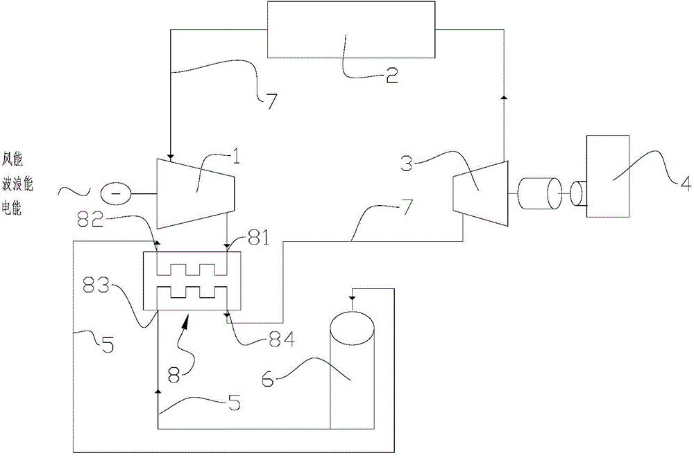
[0029] (1) During the power surplus period, the carbon dioxide gas at low pressure and normal temperature in the carbon dioxide storage 2 is compressed into high temperature and high pressure carbon dioxide gas with the compressor 1, and the energy storage device is used to store the heat released during the compression process;

[0030] (2) cooling and liquefying the high-temperature and high-pressure carbon dioxide gas and storing it in the liquid carbon dioxide storage tank 6, while the process also utilizes the energy storage device to store the heat energy released by liquefaction;

[0031] (3) When the electric power is needed, the high-pressure carbon dioxide liquid is decompressed at a constant rate to absorb the heat stored in the energy storage device and keep the temperature stable and gasified, and then directly enter the expander 3 to do work, and drive the generator 4 to generate electricity;

[...

Embodiment 2

[0039] Wind / Solar / Wave Energy Storage:

[0040] (1) Use the electricity generated by wind energy / solar energy / wave energy to compress the low-pressure and normal-temperature carbon dioxide in the carbon dioxide storage 2 into high-temperature and high-pressure carbon dioxide gas with the compressor 1, and use the energy storage device to store the heat released during the compression process;

[0041] (2) Cool down and liquefy the high-temperature and high-pressure carbon dioxide gas, and store it in the liquid carbon dioxide storage tank 6 while using the energy storage device to store the heat energy released by liquefaction;

[0042] (3) When electricity is needed (power consumption peak), the high-pressure carbon dioxide liquid is decompressed at a constant rate to absorb the heat stored in the energy storage device and gasified, and then directly passed into the expander 3 to do work, and the expander 3 drives the generator 4 power generation;

[0043] (4) Pass the low-pre...


PUM


Abstract

The invention discloses a carbon dioxide gas-liquid phase change energy storage method. The method comprises the following steps that firstly, when electric power is in surplus, carbon dioxide in a carbon dioxide warehouse is compressed and cooled to be liquefied into liquid carbon dioxide, and the thermal energy released during compressing and liquefying is stored through a phase change energy storage heat exchange system; secondly, when power is needed, the liquid carbon dioxide is gasified by reducing pressure and absorbing the thermal energy stored in the phase change energy storage heat exchange system, the gaseous carbon dioxide enters an expansion machine to act, and the expansion machine drives a power generator to generate electricity. A device for achieving method is characterized in that the carbon dioxide warehouse is connected with the phase change energy storage heat exchange system through a gaseous carbon dioxide pipeline via a compressor, a liquid carbon dioxide storage tank is connected with the phase change energy storage heat exchange system through a liquid carbon dioxide pipeline, and the phase change energy storage heat exchange system is connected with the carbon dioxide warehouse through a gaseous carbon dioxide pipeline. The gas-liquid phase change energy storage efficiency is high, and safety and reliability are achieved.

Description

technical field [0001] The invention relates to the technical field of energy storage, in particular to a carbon dioxide gas-liquid phase change energy storage method and a device for realizing the method. Background technique [0002] At present, the consumption of electricity continues to grow, but the development of electricity production capacity and the construction of transportation networks are relatively lagging behind; the share of renewable energy (wind energy, solar energy, etc.) in the total electricity supply is gradually increasing, but renewable energy The generation of energy has the disadvantage of being inherently intermittent. At present, the proportion of new energy power generation in the power grid does not exceed 10%, otherwise many problems will arise due to the instability of energy sources; on the user side, power consumption is not constant throughout the day, with peak energy consumption and These problems have increased the complexity and insecu...

Claims


Application Information

Patent Timeline
IPC IPC(8): F01K25/10F01K25/00
Inventor 李栋梁梁德青梁帅
Owner GUANGZHOU INST OF ENERGY CONVERSION - CHINESE ACAD OF SCI
Learn More