
Duplex double-circulating under-balanced drilling technology

An underbalanced drilling and double-circulation technology, which is applied to drilling equipment, driving devices for drilling in boreholes, drill pipes, etc., can solve problems such as high equipment costs, sticking of bonded drilling tools, and complex geological structures, and avoid Borehole wall collapse and the effect of increasing drilling speed

Active Publication Date: 2015-04-22
上海万维亿通装备制造有限公司
View PDF9 Cites 8 Cited by
  • Summary
  • Abstract
  • Description
  • Claims
  • Application Information

AI Technical Summary

Problems solved by technology

Air DTH hammer drilling technology mainly exists: 1. As long as the under-balanced conditions are met, the drilled open hole wall is prone to collapse, diameter shrinkage, and block loss. The downhole water and gas will produce vaporized water, and the well wall will be eroded during the upward return process to accelerate the collapse. ;2. The hole diameter of the open hole is relatively large, the geological structure is relatively complex, and the well is relatively deep and other factors, the gas consumption is too large, resulting in high equipment costs, and the cuttings carried by the gas must be dry, otherwise the sticking of the drilling tool will cause the drill to stick; 3. When the water is produced from underground formations, the greater the water output, the greater the amount of gas required and the higher the pressure

Method used


Image

  • Duplex double-circulating under-balanced drilling technology

Examples


Embodiment Construction

[0011] The compound double-circulation underbalanced drilling technology of the present invention is realized in this way, which will be described in detail below in conjunction with the accompanying drawings.

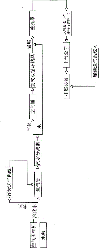
[0012] See figure 1 , compound double circulation underbalanced drilling process, according to the following steps:

[0013] (1) Drilling: start the air compressor and water pump, and vaporized water is formed in the pipeline, and the vaporized water enters the steam-water separator through the intake pipe, and the separated gas drives the air hammer to drive the compound double-circulation drilling tool to work, and the separated water The cuttings formed during the working process of the compound double-circulation drilling tool are mixed into mud, pass through the fairing, and return to the upper air box through the anti-chip channel formed by the annular space between the drill pipe and the intake pipe, and finally discharged by the chip removal device.

[0014] (...


PUM


Abstract

The invention relates to a duplex double-circulating under-balanced drilling technology. The duplex double-circulating under-balanced drilling technology is characterized by comprising the steps of drilling and making up a joint for drilling; an air compressor and a water pump are started; vaporous water generated in the pipeline enters a steam-water separator through an air inlet pipe; the separated air is used for propelling an air hammer to drive a duplex double-circulating drill to work; the separated water is mixed with rock debris generated in the work of the duplex double-circulating drill to form slurry which flows through a rectifying cover; the slurry flows through a debris returning channel formed between a drilling rod and the air inlet pipe to be returned to an upper air box and then is discharged through a debris discharging device; the step of making up the joint is that the vaporous water is reversed through a three-way valve and then enters a continuous air supply system; the vaporous water in the continuous air supply system enters a steam-water separator through the air inlet pipe; the separated air propels the air hammer to drive the duplex double-circulating drill to work. According to the technology, the separated water is mixed with the with rock debris generated in the work of the duplex double-circulating drill to form slurry which flows through the rectifying cover; the slurry flows through the debris returning channel formed between the drilling rod and the air inlet pipe to be returned to the upper air box and then the discharged through the debris discharging device.

Description

technical field [0001] The invention relates to a drilling technology suitable for oil drilling, geothermal wells, power generation wells, coalfield escape wells and other drilling operations, in particular to a compound double-circulation underbalanced drilling technology. Background technique [0002] Underbalanced drilling, also known as negative pressure drilling, refers to a drilling technique in which the bottom hole pressure is lower than the formation pressure during drilling, and the fluid in the ground enters the wellbore in a controlled manner and circulates to the surface. At present, the relatively mature underbalanced drilling technology at home and abroad mainly adopts the air down-the-hole hammer drilling technology, and its technological process is as follows: (1). DTH hammer and drilling tools work. The air discharged from the drilling tool is used to cool the drill bit and carry cuttings back to the ground from the drill pipe and the annulus of the wellbo...

Claims


Application Information

Patent Timeline
Patent Type & Authority Applications(China)
IPC IPC(8): E21B4/14E21B17/18
CPCE21B4/14E21B17/18E21B21/085
Inventor 张朝纯李万昌郑义刘英车长伟张忠涛杨东贺群张公淳李守仁杨智光计万仁张朝绪张晓黄鸿森孙立达张舒潘玉清董长舟
Owner 上海万维亿通装备制造有限公司
Learn More