Amplifying device, and wireless communication device equipped with amplifying device

A technique for amplifying devices and amplifiers, applied to components of amplifying devices, amplifiers, high-frequency amplifiers, etc.

Inactive Publication Date: 2015-04-15
SHARP KK
View PDF8 Cites 6 Cited by
  • Summary
  • Abstract
  • Description
  • Claims
  • Application Information

AI Technical Summary

Problems solved by technology

like Figure 9 As shown, when the actual use loss is specified below 0.7dB, the required performance can only be obtained in the narrow range of 849MHz-963MHz
[0013] Broadband can be achieved by multi-stage matching elements, however, as described in JP-A-2011-35761 (Patent Document 1), for example, the relative bandwidth of ±10-20% is generally the limit
That is, in terms of the GSM frequency band, although GSM800 and 900, GSM1800 and 1900 can be realized by using one power amplifier each, and a total of two power amplifiers, it is impossible to realize all four frequency bands by using one power amplifier in the prior art. frequency band

Method used


Image

  • Amplifying device, and wireless communication device equipped with amplifying device
  • Amplifying device, and wireless communication device equipped with amplifying device
  • Amplifying device, and wireless communication device equipped with amplifying device

Examples


Embodiment Construction

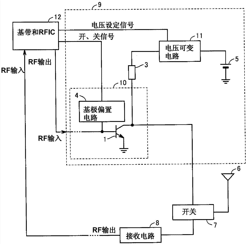
[0034] figure 1 It is a block diagram showing the configuration of the most basic wireless communication device using the high-frequency power amplifier of the present invention. Also, for the above Figure 7 with Figure 8 Structures of the same type as those described in , are denoted by the same symbols.

[0035] figure 1 The wireless communication device described in has: an antenna 6 for transmitting and receiving data such as voice and data communication by wireless communication; a switch 7 designed to share the antenna 6 when transmitting and receiving; connected to the switch 7, and is input and received A data reception circuit 8; a transmission circuit 9 connected to a switch 7 to output transmission data; and an IC 12 integrally formed with a baseband IC and an RFIC. In addition, the baseband IC and the RFIC may also be formed separately (separately).

[0036] The transmission circuit 9 includes: a high-frequency power amplifier 10 for amplifying data signals...


PUM


Abstract

Supply of the collector electrode of a transistor (1) used for amplification is supplied by voltage converted by a DC / DC converter (11). The output voltage of the DC / DC converter (11) is determined by input impedance of a post-stage circuit module, for example, voltage of the DC / DC converter (11) is set, so for input impedance (generally 50 [omega]) of the post-stage circuit module, even though an output matching circuit is not used, output waveform of an amplification circuit becomes proper when being used as a modulation method (mode) of an object or using frequency (frequency band).

Description

technical field [0001] The present invention relates to an amplifying device and a wireless communication device equipped with the amplifying device, and particularly relates to a technique for amplifying power while matching impedance with impedance. Background technique [0002] In wireless communication devices such as mobile phones and wireless LANs (Local Area Networks), data such as voice and data communications are amplified by power amplifiers and transmitted to base stations or other communication devices. [0003] The frequency of microwaves is assigned to these wireless communications, and the power amplifier is adjusted so that a predetermined power signal can be output at the frequency used with predetermined performance, especially predetermined distortion characteristics. In RF circuits using microwaves, when components with different characteristic impedances are connected, signal loss due to mismatch will occur. Therefore, the matching of the input and outpu...

Claims


Application Information

Patent Timeline
Patent Type & Authority Applications(China)
IPC IPC(8): H03F3/24H03F3/60H04B1/04
CPCH03F3/245H04B1/0458H03F1/0272H03F2200/181H03F3/189H03F1/0277H03F3/72H03F2203/7227H03F2200/151H03F2200/111H03F2200/408H03F3/19H03F2200/451H03F2200/504H03F3/21
Inventor 原信二
Owner SHARP KK
Why Eureka
Try Eureka