
Waste heat recovery device

A waste heat recovery device and heat exchanger technology, which can be used in drying gas layout, lighting and heating equipment, dryers, etc., can solve problems such as waste and reuse of anion exchangers, and achieve the effect of reducing steam consumption.

Inactive Publication Date: 2015-04-15
李英华
View PDF0 Cites 2 Cited by
  • Summary
  • Abstract
  • Description
  • Claims
  • Application Information

AI Technical Summary

Problems solved by technology

At present, when producing monoammonium phosphate products, most of the steam condensate in the first-effect heat exchanger in the concentration unit is sent back to the condensate tank, but because the water temperature is too high, it cannot be sent to the anion exchanger for direct reuse, resulting in waste

Method used


Image

  • Waste heat recovery device

Examples


Embodiment Construction

[0009] The following examples illustrate the present invention in more detail, but are not limited to the following examples as long as it falls within the scope of the present invention.

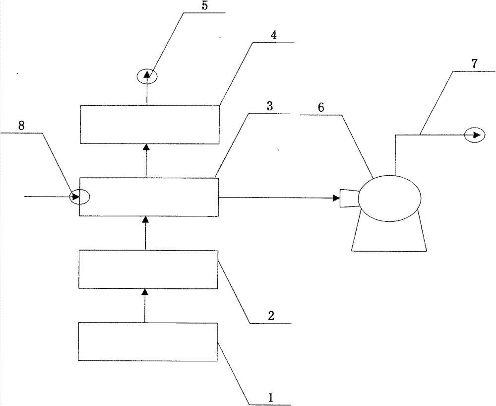
[0010] A waste heat recovery device, comprising a one-effect heat exchanger (1), a condensed water tank (2), a tubular water heater (3), a cooled condensed water tank (4), a desalinated water station port (5 ), a drying blower (6), a hot air delivery pipe (7), and an air inlet pipe (8). The one-effect heat exchanger (1) is sequentially connected with a condensed water tank (2), a shell and tube water heater (3), and a cooled condensed water tank (4), and one end of the shell and tube water heater (3) is connected to There is an air input pipe (8), one end is connected to the drying fan (6), the cooled condensate tank (4) is connected to the desalinated water station port (5), and the hot air delivery pipe (7) is located on the drying fan (6) .

[0011] The above-described embodiment is on...


PUM


Abstract

The invention discloses a waste heat recovery device. The waste heat recovery device is composed of a first effect heat exchanger (1), a condensation water tank (2), a tubular water heater (3), a condensation water tank (4) used after temperature is reduced, a desalted water removal station port (5), a drying fan (6), a hot wind conveying pipe (7) and an air conveying pipe (8), wherein the condensation water tank (2), the tubular water heater (3) and the condensation water tank (4) used after the temperature is reduced are sequentially connected with the rear of the first effect heat exchanger (1), one end of the tubular water heater (3) is connected with the air conveying pipe (8), the other end of the tubular water heater (3) is connected with the drying fan (6), the condensation water tank (4) used after the temperature is reduced is connected with the desalted water removal station port (5), and the hot wind conveying pipe (7) is located on the drying fan (6). The waste heat recovery device can effectively reduce energy consumption, reduce pollutant emission, reduce production cost of a product, improve production effectiveness, and achieve double winning of economic effectiveness improvement, and energy conservation and environment protection.

Description

technical field [0001] The invention relates to the field of energy regeneration, in particular to a waste heat recovery device. Background technique [0002] In the 21st century, the scientific outlook on development has become the guiding ideology of our economic development, and energy conservation and environmental protection are also particularly important. Energy conservation and emission reduction, as well as improving the comprehensive utilization rate of energy, are the fundamental ways to solve my country's energy problems, and they are in a priority development position. At present, there are still many problems in my country's energy recovery and utilization, such as low utilization rate, poor economic benefits, and high pressure on the ecological environment. Waste heat resources belong to secondary energy, which is the product of primary energy or combustible material conversion, or the heat released during fuel combustion after completing a certain process. ...

Claims


Application Information

Patent Timeline
IPC IPC(8): F26B21/00
CPCY02P70/10
Inventor 李英华
Owner 李英华
Learn More