
Indoor air purifying method and indoor air purifying device

A technology for purifying device and indoor air, applied in the field of air purification, can solve the problems of poor uniformity of droplet particle size, difficult to effectively control the amount of charge, clogging of fine nozzles, etc., and achieve the effect of improving absorption efficiency

Inactive Publication Date: 2015-04-08
JIANGSU UNIV
View PDF7 Cites 14 Cited by
  • Summary
  • Abstract
  • Description
  • Claims
  • Application Information

AI Technical Summary

Problems solved by technology

This method is a comprehensive application of physical adsorption and chemical reaction, but the structure is complex and it is difficult to form small products
[0005] The Chinese application number is 2012103929294, and the patent document titled "A Device and Method for Purifying Indoor Air with Electrostatic Atomization" discloses a method that combines electrostatic dust removal purification with electrostatic atomization water washing purification, and the air first passes through the filter screen. In the strong electric field area formed by high-voltage corona, harmful gases are decomposed by the electric field, and then pass through the charged water mist area formed by electrostatic atomization to further dissolve harmful gases, absorb dust particles, and then be deeply purified by the photocatalyst filter. Negative ion generation and airflow guidance achieve the purpose of efficient purification of indoor air circulation; however, it is difficult to effectively control the charge quantity of the charged mist generated by the electrostatic capillary, and the particle size uniformity of the mist formed by the charge is poor, and the fine nozzles used are easy to produce Problems such as clogging, and fluid supplementation is required

Method used


Image

  • Indoor air purifying method and indoor air purifying device
  • Indoor air purifying method and indoor air purifying device
  • Indoor air purifying method and indoor air purifying device

Examples


Embodiment Construction

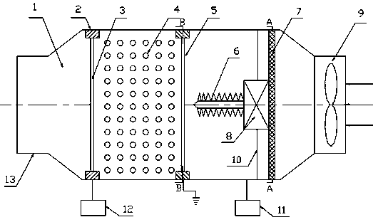
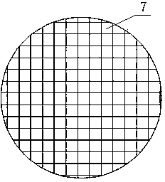
[0022] see figure 1 , an indoor air purification device of the present invention has an exhaust gas and fine particle adsorption cylinder 1, and the adsorption cylinder 1 is circular or square. The front end of the adsorption cylinder 1 is an air inlet, and the rear end is an air outlet 13 . An induced draft fan 9 is installed at the air inlet, and the induced draft fan 9 provides power for the movement of the airflow. Inside the cylinder of the adsorption cylinder 1, in the direction from the front to the rear from the air inlet to the air outlet 13, the coarse filter screen 7, the prickly corona discharge electrode 6, Mesh ground electrode 5 , filling layer 4 and mesh charge electrode 3 .

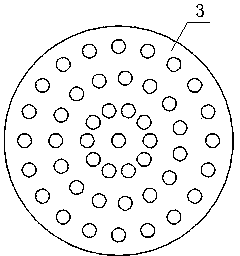
[0023] The rear end of the filling layer 4 is arranged with a mesh charging electrode 3, and the front end is arranged with a mesh ground electrode 5. The mesh charging electrode 3 is externally connected to a high-voltage pulse electrostatic generator 12 through an insulated wire, and ...


PUM

PropertyMeasurementUnit
Diameteraaaaaaaaaa

Abstract

The invention discloses an indoor air purifying method and an indoor air purifying device. A primary strainer, a barbed nail corona discharging electrode, a mesh grounding electrode, a filling layer and a mesh charging electrode, wherein the filling layer is filled with high-power medium particles; the mesh charging electrode is arranged at the rear end of the filling layer; the mesh grounding electrode is arranged at the front end of the filling layer; the mesh charging electrode is in external connection with a high-voltage pulse electrostatic generator through an insulated conductor; the mesh grounding electrode is in external connection with the ground through an insulated conductor; the outer wall of the primary strainer clings to the inner wall of an absorbing barrel; and the barbed nail corona discharging electrode is arranged in space between the primary strainer and the mesh grounding electrode and is connected with the high-voltage electrostatic generator positioned outside the absorbing barrel. Dusty airflow and high-power medium balls are respectively treated by a corona discharging method and a pulse corona discharging method, and bacteria are effectively killed by streamer corona generated on surfaces of the medium balls while the particles are absorbed by the streamer corona.

Description

technical field [0001] The invention relates to indoor air purification technology, in particular to an air purification method and device for purifying indoor air by adopting corona discharge technology. Background technique [0002] With the frequent occurrence of smog weather and inhalable particles, formaldehyde, mites, etc. produced by decoration, the air quality has affected people's health, so indoor air must be purified. Existing indoor air purification technologies mainly include physical adsorption technology, HEPA high-efficiency filtration technology, photocatalyst purification technology, electrostatic dust collection technology and electrostatic fine water mist dust removal technology. Physical adsorption uses activated carbon, zeolite, and silica gel with high specific area porous media materials to absorb inhalable particulate matter and dust in the air, but the material is easy to cause pollutants to be re-emitted after adsorption saturation, forming seconda...

Claims


Application Information

Patent Timeline
IPC IPC(8): F24F1/02F24F13/28
CPCF24F8/10F24F8/192F24F8/20
Inventor 王贞涛朱忠辉郭天宇张永辉闻建龙
Owner JIANGSU UNIV
Learn More