
Structure and construction process for reducing power impact response at back of seamless bridge abutment

A technology of seamless bridge and dynamic shock, applied in bridges, bridge parts, bridge construction, etc., can solve the problems of poor settlement of transition sections of seamless bridges, large settlement and deformation of flexible structures, etc., to avoid poor settlement of roads and bridges, avoid bridge head The effect of jumping and reducing additional stress

Inactive Publication Date: 2015-04-08
FUZHOU UNIV
View PDF4 Cites 7 Cited by
  • Summary
  • Abstract
  • Description
  • Claims
  • Application Information

AI Technical Summary

Problems solved by technology

Seamless bridges have higher requirements on the foundation. Generally, a solid support is required under the pier abutment, so that the settlement and displacement at the abutment can be ignored; while the stiffness of the road subgrade itself is smaller than that of the bridge, the subgrade under the subgrade is less rigid than the bridge. The soil foundation is generally loose and belongs to the flexible foundation. Under the same road surface weight and vehicle load, the dynamic response of the soil foundation is different, and the deformation that may occur over time is also different. Flexible structures The settlement deformation is relatively large, which will inevitably cause the settlement difference on the transition section of the seamless bridge

Method used


Image

  • Structure and construction process for reducing power impact response at back of seamless bridge abutment
  • Structure and construction process for reducing power impact response at back of seamless bridge abutment

Examples


Embodiment Construction

[0021] In order to make the above-mentioned features and advantages of the present invention more comprehensible, the following specific embodiments are described in detail with reference to the accompanying drawings.

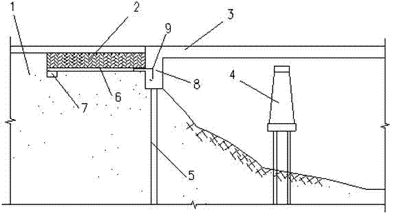
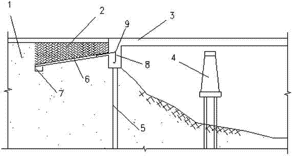
[0022] refer to Figure 1 to Figure 2 , the present invention relates to a structure for reducing the dynamic impact response behind the abutment of a seamless bridge, including a slab, a seamless bridge and a soil foundation, the slab is buried in a certain depth of filling soil behind the abutment, and the steel bar is connected to the back wall Integral connection, backfill with light weight, good hardening, low compressibility, fast compaction, and strong water permeability materials to absorb part of the impact energy and reduce the impact of passing vehicles on the slab, using embedded slabs The covering soil within the length range and the soil at the end of the board form a common thick and long elastic body to absorb the expansion and contraction defor...


PUM


Abstract

The invention discloses a structure and a construction process for reducing power impact response at the back of a seamless bridge abutment. A slab is buried in the filling at the back of an abutment and is integrally connected with a back wall. The top part of the buried slab is provided with a back filling layer to distribute part of impact load and reduce the impact effect on the slab. Cover soil in the length range of the buried slab and a soil body at the end of the slab together form a thick and long elastic body to absorb the expansion deformation of a girder body. By the structure and construction process for reducing power impact response at the back of the seamless bridge abutment, load of vehicles on the bridge is distributed, the direct effect impact of vehicles on the slab is decreased, and the slab can be prevented from breaking down. Because the slab bears part of overburden load, subsidiary stress on a lower soil matrix is reduced, post-construction settlement of the soil matrix is decreased, large bridge settlement difference of the bridge is avoided, the settlement of the transaction section of the seamless bridge is transformed from a sharp change to a gradual change, and bumping at bridgehead is avoided. Moreover, the seismic performance of the seamless bridge is improved. Therefore, the structure and the construction process for reducing power impact response at the back of the seamless bridge abutment are particularly applicable to integral seamless bridges.

Description

technical field [0001] The invention relates to a structure for reducing the dynamic impact response behind a seamless bridge abutment and a construction process thereof, which is particularly suitable for an integral abutment seamless bridge and belongs to the field of bridges. Background technique [0002] The transition section of the seamless bridge is the link between the abutment and the subgrade, and the stiffness of the two is different. Seamless bridges have higher requirements on the foundation. Generally, a solid support is required under the pier abutment, so that the settlement and displacement at the abutment can be ignored; while the stiffness of the road foundation itself is smaller than that of the bridge, the The soil foundation is generally loose and belongs to the flexible foundation. Under the same road surface weight and vehicle load, the dynamic response of the soil foundation is different, and the deformation that may occur over time is also different...

Claims


Application Information

Patent Timeline
Patent Type & Authority Applications(China)
IPC IPC(8): E01D19/02E01D21/00
CPCE01D19/00E01D21/00
Inventor 庄一舟韩裕添王胜智陈斌
Owner FUZHOU UNIV
Learn More