Processing machine tool and magnetostriction-based precise feeding driving device
A technology of feed drive and magnetic drive, which is applied in the direction of drive devices, metal processing machinery parts, metal processing equipment, etc., can solve the problems of conductive slip rings not being in electrical contact, low reliability, complex device structure, etc., to achieve Improve the accuracy of telescopic displacement, improve the reliability of the device, and the effect of accurate displacement output
- Summary
- Abstract
- Description
- Claims
- Application Information
AI Technical Summary
Problems solved by technology
Method used
Image
Examples
Embodiment 1
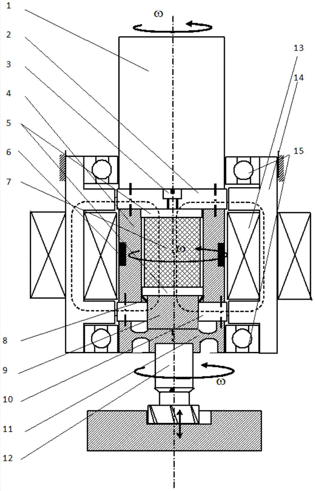
[0082] Such as figure 1 As shown, this embodiment provides a precision feed drive device based on magnetostriction, including a magnetostrictive drive shaft and a ring magnetic field generating device arranged outside the magnetic drive shaft. The ring magnetic field generator Relative rotation with the magnetic drive shaft; where:
[0083] The magnetic drive shaft body includes: an upper rigid connector 2, a preload adjustment member 3, a magnetic frame body 4, a magnetic displacement drive mechanism 7, a displacement output rod 9, a lower rigid connector 10 and an elastic end cover part 11 , the magneto-induced frame body 4 is rigidly connected between the upper rigid connector 2 and the lower rigid connector 10, the magneto-induced displacement drive mechanism 7 is arranged in the magneto-induced frame body 4, and the magneto-induced displacement drive mechanism 7 The lower end of the displacement output rod 9 is connected, and the output end of the displacement output rod...
Embodiment 2
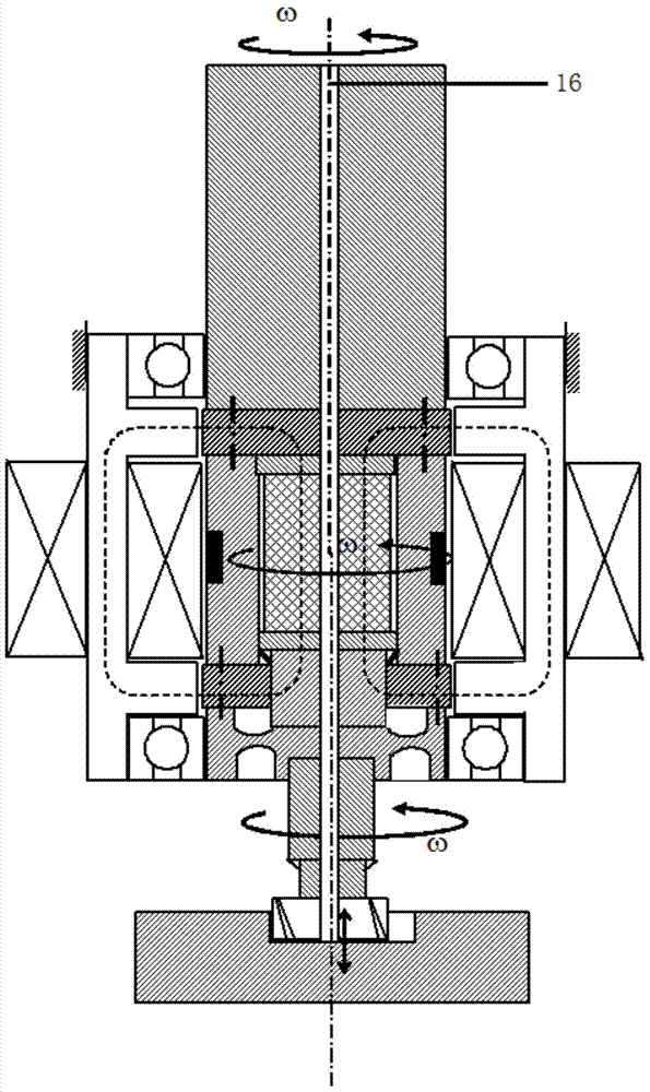
[0110] Embodiment 2 is a variation of embodiment 1, and its working principle is the same as that of embodiment 1.
[0111] On the basis of embodiment 1, this embodiment differs from embodiment 1 in that:
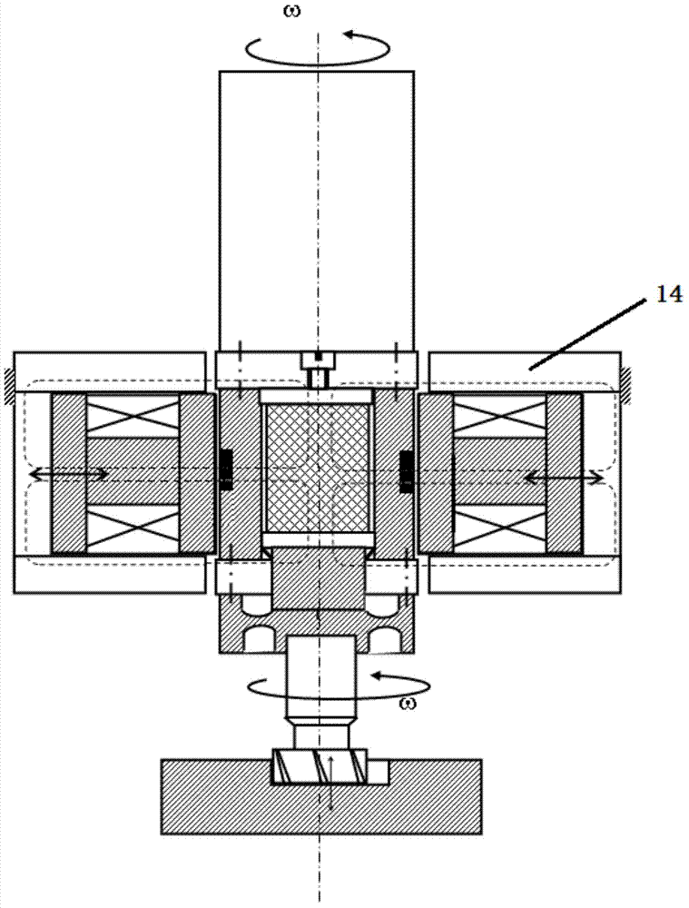
[0112] In this embodiment, the ring magnetic field generating device includes: a movable magnetic actuator and a rigid frame magnetic circuit structure, the movable magnetic actuator is arranged inside the rigid frame magnetic circuit structure, and the rigid frame The outer part of the magnetic circuit structure is fixed, and the movable magnetic actuator approaches or moves away from the magnetically actuated drive shaft, which can also play a role in locking the magnetically actuated drive shaft while adjusting the strength of the magnetic field.
[0113] Further, the movable magnetic actuator adopts the following form:
[0114] A pair of electromagnetic coils or a pair of permanent magnets for symmetrically applying an excitation magnetic field, and the pair of electro...
Embodiment 3
[0117] Embodiment 3 is a variation of Embodiment 2.
[0118] On the basis of embodiment 2, this embodiment differs from embodiment 2 in that:
[0119] The movable magnetic actuator adopts the following form:
[0120] An independent electromagnetic coil, the independent electromagnetic coil is sleeved on the outside of the magnetic drive shaft body.
[0121] In this embodiment, the magnetic frame body is a non-magnetic material body, and a closed magnetic circuit is formed among the rigid frame magnetic circuit structure, the upper rigid connector, the magnetic displacement drive mechanism, and the lower rigid connector. Such as Figure 4 shown.
PUM
 Abstract
Description
Claims
Application Information
 - R&D
- Intellectual Property
- Life Sciences
- Materials
- Tech Scout
- Unparalleled Data Quality
- Higher Quality Content
- 60% Fewer Hallucinations
Browse by: Latest US Patents, China's latest patents, Technical Efficacy Thesaurus, Application Domain, Technology Topic, Popular Technical Reports.
© 2025 PatSnap. All rights reserved.Legal|Privacy policy|Modern Slavery Act Transparency Statement|Sitemap|About US| Contact US: help@patsnap.com


