A downstream non-winding spiral line defogging device
The technology of a defogging device and non-twisting vortex is applied in the field of downstream non-twisting spiral defogging devices, which can solve the problem of the large area of the electrostatic demister, the low efficiency of the baffle demister, and the cyclone demister. Large resistance and other problems, to achieve the effects of high demisting efficiency, small over-current resistance loss and strong engineering reliability
- Summary
- Abstract
- Description
- Claims
- Application Information
AI Technical Summary
Problems solved by technology
Method used
Image
Examples
Embodiment 1
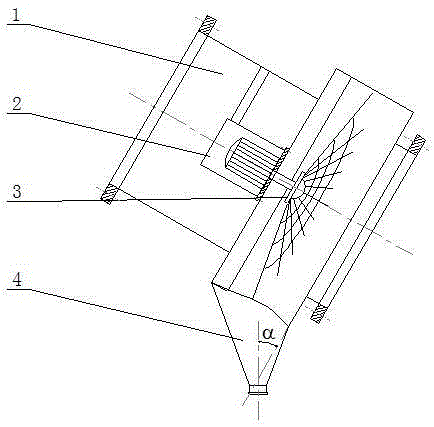
[0039] Disclosed is a downstream non-winding spiral line defogging device. Such as figure 1 As shown, the demisting device is composed of a housing 1 , a sealed box 2 , a rotating device 3 and a water collecting box 4 .
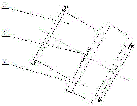
[0040] Such as image 3 As shown, the housing 1 includes a small round tube 5, a mounting bracket 6 and a large round tube 7, the small round tube 5 and the large round tube 7 are airtightly and fixedly connected to the center, and the inner wall of the large round tube 7 is fixed with the mounting bracket 6. Such as Figure 4 As shown, the mounting frame 6 is composed of two parallel steel beams 8 and a mounting plate 9 . Such as image 3 and Figure 4 As shown, the mounting plate 9 is fixed at the middle position of two parallel steel beams 8, and the two steel beams 8 are close to the end faces of the small round tubes 5. The pipe wall of the large round pipe 7 is provided with a water collecting tank connecting hole, and the two ends of the housing ...
Embodiment 2
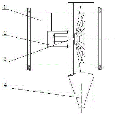
[0049] Disclosed is a downstream non-winding spiral line defogging device. Such as figure 2 As shown, the demisting device is composed of a housing 1 , a sealed box 2 , a rotating device 3 and a water collecting box 4 . The structures of the casing 1, the sealing box 2 and the rotating device 3 are the same as those of the first embodiment.
[0050] Such as Figure 9 As shown, the water collection box 4 is funnel-shaped, and the big end of the water collection box 4 is welded as one with the water collection box connection hole of the large round pipe 7 of the housing 1, and the small end of the water collection box 4 is equipped with a valve body. The included angle α=0° between the central axis of the water collecting tank 4 and the end face of the large round pipe 7 of the housing 1 means that the connected flue is a horizontal flue.
[0051] The diameter of the disc 15 is 25-30mm larger than the diameter of the hemispherical shell 17, and 20-32 wiring holes are uniform...
Embodiment 3
[0056] Disclosed is a downstream non-winding spiral line defogging device. Except following technical parameter, all the other are with embodiment 1:
[0057] The included angle α between the central axis of the water collecting tank 4 and the end face of the large round pipe 7 of the housing 1 is greater than 0° and less than 30°, or the included angle α between the central axis of the water collecting tank 4 and the end face of the large round pipe 7 of the housing 1 is greater than 30° and less than 45°.
[0058] Compared with the prior art, this specific embodiment has the following beneficial effects:
[0059] (1) When the mist-containing smoke passes through the high-speed rotating fiber net 14, it collides with the fiber net 14, is intercepted by the fiber net 14, and is thrown to the wall of the large round tube 7 along the warp under the action of centrifugal force; The separated water and dust particles flow into the water collection tank 4 along the pipe wall of t...
PUM
 Abstract
Description
Claims
Application Information
 - R&D
- Intellectual Property
- Life Sciences
- Materials
- Tech Scout
- Unparalleled Data Quality
- Higher Quality Content
- 60% Fewer Hallucinations
Browse by: Latest US Patents, China's latest patents, Technical Efficacy Thesaurus, Application Domain, Technology Topic, Popular Technical Reports.
© 2025 PatSnap. All rights reserved.Legal|Privacy policy|Modern Slavery Act Transparency Statement|Sitemap|About US| Contact US: help@patsnap.com


