Double-layer detachable shot blasting machine roller way tool bracket

A detachable, shot blasting machine technology, applied in the field of steel structure manufacturing, can solve the problems of stuck in the round roller, downtime, and reduced production efficiency, and achieve the effects of preventing workpieces from falling, increasing the amount of feeding, and improving production efficiency.

Inactive Publication Date: 2015-04-01
KOCEL STEEL STRUCTURE CO LTD
View PDF8 Cites 1 Cited by
  • Summary
  • Abstract
  • Description
  • Claims
  • Application Information

AI Technical Summary

Problems solved by technology

[0004] The purpose of the present invention is to provide a double-layer detachable shot blasting machine roller table tooling bracket to improve the prior art because the components are stuck in the round roller during the process of conveying to the roller table, resulting in unnecessary downtime and reduced production efficiency. The problem

Method used


Image

  • Double-layer detachable shot blasting machine roller way tool bracket
  • Double-layer detachable shot blasting machine roller way tool bracket
  • Double-layer detachable shot blasting machine roller way tool bracket

Examples


Embodiment 1

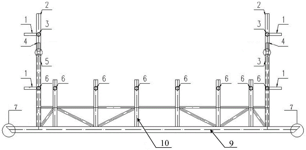
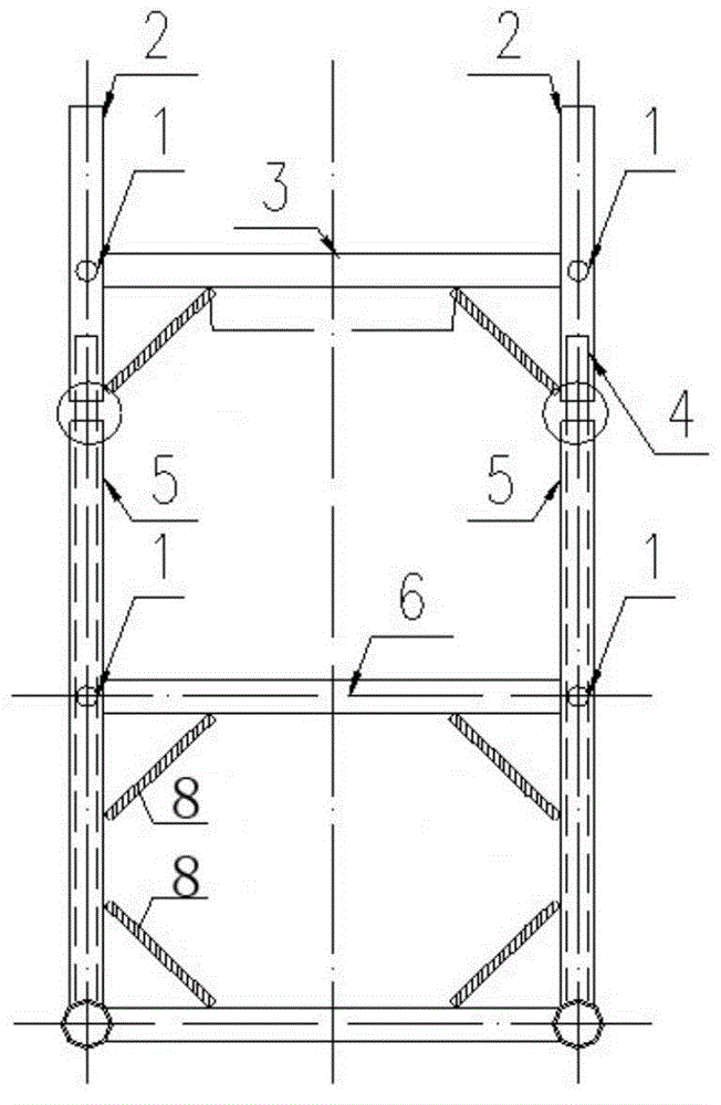
[0024] Such as figure 1 , figure 2 As shown, the embodiment of the present invention mainly improves the structure of the roller table tooling bracket of the shot blasting machine, which mainly includes handrails 1, a first-level horizontal bar 6, a first-level vertical bar 5, a second-level horizontal bar 3, and a second-level vertical bar 2 and roller table support 9.

[0025] Wherein, there are at least two roller table supports 9, and its two ends are installed on the roller table. Mouth 7; the quantity of one layer of vertical rod 5 is at least twice of the quantity of roller table support 9, and the lower ends of two layers of vertical rod 5 are respectively vertically installed on the same roller table support 9 both sides ends (here the end is not the top , refers to the position near the top), and the one-layer vertical rods 5 installed on the same side end of each roller table bracket 9 are parallel to each other and perpendicular to the plane where each roller ta...

Embodiment 2

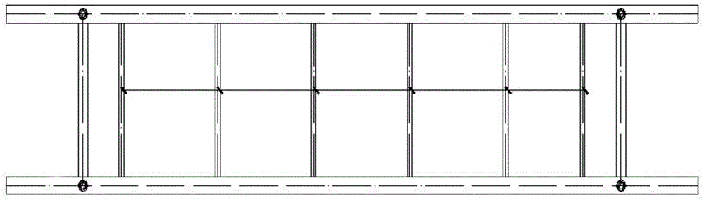
[0030] Such as figure 1 , image 3 As shown, the present embodiment carries out the following extensions on the basis of Embodiment 1, between two layers of vertical rods 5 at both ends of the same roller table bracket 9, along the roller table bracket 9, and one layer of vertical rods are sequentially fixed. Bar 5 is parallel to the mounting bar 10, and between the mounting bars 10 fixed on different roller table supports 9, the same cross bar as the height of one layer of cross bar 6 is installed, as preferably, the mounting bars on different roller table supports 9 10 are arranged at the same interval, and the cross bars fixed between the installation bars 10 are arranged to be parallel to the cross bars 6 of one floor. That is, improve the density of one deck of cross bars 6, except the one deck of cross bars 6 installed between one deck of upright bars 5, install a plurality of installation bars 10 for adding one deck of cross bars 6 (cross bars).

[0031] According to ...


PUM


Abstract

The invention provides a double-layer detachable shot blasting machine roller way tool bracket, which is used for improving the problem that the production efficiency is reduced caused by unnecessary downtime because a component is clamped to a round roller when being conveyed to the roller way. The double-layer detachable shot blasting machine roller way tool bracket comprises cross rods at the first layers, vertical rods at the first layers, cross rods at the second layers, vertical rods at the second layers and roller way supports; the lower ends of every two vertical rods at the first layers are respectively perpendicularly installed on the end parts at two sides of the same roller way support; the vertical rods at the first layers, installed on the end part at the same side of each roller way support, are parallel with each other, and are perpendicular to a plane, on which the roller way supports are located; the lower ends of the vertical rods at the second layers are perpendicularly connected with the upper ends of the vertical rods at the first layers in a detachable mode; the cross rods at the first layers are fixed between the vertical rods at the first layers, installed on the end parts of the same side of different roller way supports; the cross rods at the second layers are fixed between the vertical rods at the second layers, installed on the end parts at the same side of different roller way supports. The double-layer detachable shot blasting machine roller way tool bracket can be used for increasing the feed amount and improving the shot blasting efficiency, is simple in structure, is convenient to implement, and is easy to popularize and apply.

Description

technical field [0001] The invention relates to the design of a tooling bracket in the field of steel structure manufacturing, in particular to a double-layer detachable roller table tooling bracket for a shot blasting machine. Background technique [0002] In the prior art, in the steel structure processing plant, the components must undergo derusting, surface painting and anti-corrosion treatment, which requires the use of high-efficiency shot blasting machines. For the surface quality of the steel plate after derusting, it is generally required to reach the Sa2.5 level (the derusting degree of the surface reaches more than 95%) in the ISO8501 standard (corresponding standards for painting, corrosion protection and surface treatment). [0003] After derusting by equipment shot blasting, the bonding strength between the paint film of the steel structure protected by spray paint and the steel body is greatly improved, and there is no peeling off after a scratch test of 1 squ...

Claims


Application Information

Patent Timeline
Patent Type & Authority Applications(China)
IPC IPC(8): B24C9/00
CPCB24C9/00
Inventor 朱蕾靳毅马龙黄戴春徐蒙
Owner KOCEL STEEL STRUCTURE CO LTD
Why Eureka
Try Eureka