Heating method of fuel oil

A heating method and fuel oil technology, applied in fuel heat treatment devices, liquid fuel feeders, charging systems, etc., can solve problems such as becoming a vacuum, increasing the viscosity of fuel oil, and being difficult to transport

Active Publication Date: 2015-03-25
HOKUSHIN ENG
View PDF1 Cites 13 Cited by
  • Summary
  • Abstract
  • Description
  • Claims
  • Application Information

AI Technical Summary

Problems solved by technology

[0007] However, in places such as cold waters, insufficient heating of the fuel oil in the storage tank 1 to be transported occurs, so the viscosity of the fuel oil flowing in the transport pipe 2 increases, and the suction resistance becomes large. Suction pressure becomes vacuum and becomes difficult to deliver

Method used


Image

  • Heating method of fuel oil
  • Heating method of fuel oil

Examples


Embodiment Construction

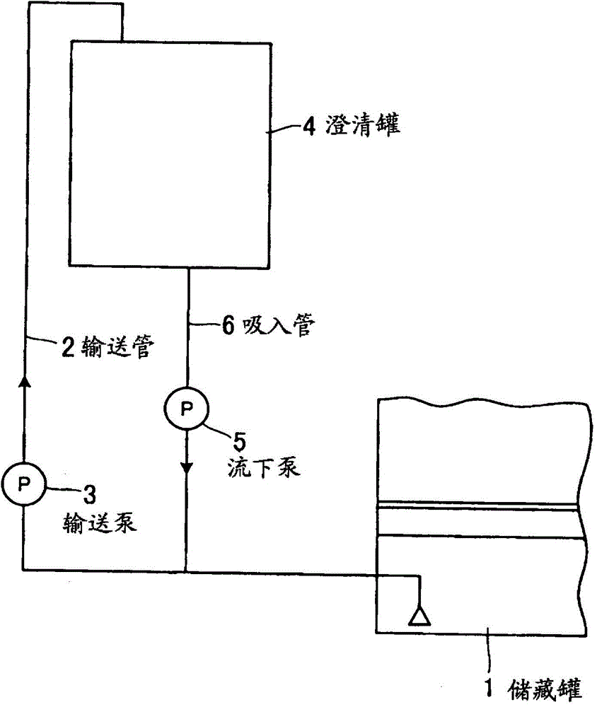
[0022] figure 1 It is a flow chart showing the heating system of the fuel oil in the storage tank. First, a desired amount of fuel oil such as C-heavy oil is charged into the storage tank 1, and at the same time, a fuel oil (not shown) built in the clarification tank 4 is used. The heated device heats the fuel oil in the clarification tank 4 , and the heated fuel oil flows down into the storage tank 1 through the suction pipe 6 by the operation of the downflow pump 5 . In the storage tank 1, the stored fuel oil and the heated fuel oil flowing down are partially mixed and partially heated to 36°C to 40°C. This heating reduces the viscosity of the fuel oil.

[0023] Next, the partially heated fuel oil in the storage tank 1 passes through the delivery pipe 2 and is delivered to the clarification tank 4 in the direction of the arrow by the operation of the delivery pump 3 . The fuel oil delivered to the clarification tank 4 is heated to a desired temperature by a heating device...


PUM


Abstract

The present invention aims for improving power load of a delivery pump and reducing absorbing resistance of a delivery pipe. When the delivery pump (3) of the fuel oil is used for delivering, a downflow pump (5) is kept to operate continuously, so that the high temperature oil form the downflow pump (5) is mixed and delivered to the fuel oil form a storage tank (1) and absorbed by the delivery pump (3) so that the viscosity of the fuel oil is reduced, and therefore the power load of the delivery pump (3) is improved, the delivery amount of the fuel oil form the storage tank (1) is reduced as much as the amount of the downflow oil, the delivery speed of the storage tank is reduced and the absorbing resistance is reduced.

Description

technical field [0001] The present invention relates to a heating method of fuel oil in a storage tank of a ship, etc., and more specifically relates to transferring fuel oil such as C heavy oil from a storage tank to a clarification tank through a delivery pipe through a delivery pump and heating it, which will be described here The method of heating the heated fuel oil mixed with the fuel oil flowing down from the clarifier tank through the suction pipe through the suction pipe, in particular, involves improving the power load of the transfer pump and reducing the suction resistance of the transfer pipe A method of heating fuel oil in a storage tank. Background technique [0002] In ships etc., when fuel oil is supplied to the engine, the fuel oil is usually sent from the fuel oil storage tank to the fuel oil clarification tank through the delivery pipe by the delivery pump, where the fuel oil is heated and passed through the fuel oil normal tank. (Fuel tank from which fu...

Claims


Application Information

Patent Timeline
Patent Type & Authority Applications(China)
IPC IPC(8): B63H21/38
CPCF02M31/10F02M31/16F02M37/04
Inventor 千千波孝泰
Owner HOKUSHIN ENG
Why Eureka
Try Eureka