
Denitration demisting device and method after wet desulfurization

A technology of wet desulfurization and demisting devices, which is applied in the direction of combined devices, separation methods, chemical instruments and methods, etc., to achieve the effects of improving NOx mass transfer and absorption capacity, improving demisting effect, and improving reaction efficiency

Active Publication Date: 2015-03-25
江苏富春江环保热电有限公司
View PDF7 Cites 3 Cited by
  • Summary
  • Abstract
  • Description
  • Claims
  • Application Information

AI Technical Summary

Problems solved by technology

[0007] The purpose of the present invention is to provide a high-efficiency and low-resistance denitrification and demisting device and method after wet desulfurization, which can simultaneously realize denitrification and demisting of flue gas after wet desulfurization, so as to solve the pollutants after wet desulfurization of small and medium-sized boilers further removal of the problem

Method used


Image

  • Denitration demisting device and method after wet desulfurization
  • Denitration demisting device and method after wet desulfurization
  • Denitration demisting device and method after wet desulfurization

Examples


Embodiment 1

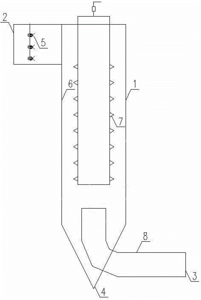
[0030] Embodiment 1, figure 1A device and method for denitrification and demisting after wet desulfurization are given, which combine the two functions of denitrification and demisting.

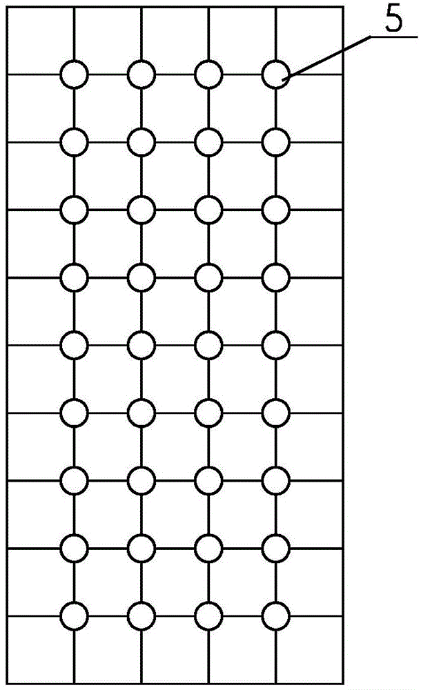
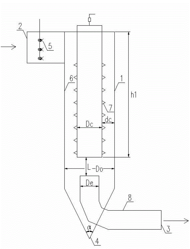
[0031] The denitrification and demisting device and method after wet desulfurization of the present invention include a cylinder body 1, which is a cylindrical inner chamber (through the cylindrical inner chamber, the airflow entering the cylinder body 1 from the side can be Form the movement mode of the helix), the cylindrical inner cavity of the cylinder body 1 is provided with an electrostatic field (ie, an electrostatic channel), and the electrostatic field is composed of two parts, one of which is the cylindrical inner cavity of the cylinder body 1 The discharge electrode plate 6 composed of the wall, and the other part is the guide electrode 7, the guide electrode 7 is a prickly electrode, that is, it is formed by adding a plurality of rows of regular pricks on the cylindrical guide col...


PUM


Abstract

The invention discloses a denitration demisting device after wet desulfurization. The denitration demisting device comprises a cylinder, wherein an air inlet and an air outlet are respectively formed in the upper and lower ends of the cylinder; the device consists of a denitration part for performing denitration on flue gas subjected to the wet desulfurization, and a demisting part for demisting the flue gas subjected to the wet desulfurization; the denitration part for performing the denitration on the flue gas subjected to the wet desulfurization comprises a nozzle for spraying an oxidizing agent and an electrostatic channel; the demisting part for demisting the flue gas subjected to the wet desulfurization comprises an electrostatic channel through which wet flue gas does a spiral motion from top to bottom; an electrostatic channel is formed in the cylinder; a nozzle is arranged in the air inlet; the air inlet is mutually connected with the cylinder by virtue of a volute type air inlet pipe; the volute type air inlet pipe penetrates through the side wall of the cylinder and is communicated with the electrostatic channel; and the air outlet penetrates through the lower end surface of the cylinder and is communicated with the electrostatic channel.

Description

technical field [0001] The invention relates to a reactor for treating flue gas of a coal-fired boiler, in particular to a denitrification and demisting device and method after wet desulfurization. Background technique [0002] my country is a big country that uses coal, but the SO emitted from coal combustion 2 , NO x Gaseous pollutants such as gaseous pollutants not only endanger the environment, but also restrict the sustainable development of the national economy and society. Therefore, basic research and technological development aimed at solving the control of coal-fired air pollutants have always attracted attention. [0003] Flue gas desulfurization technology mainly includes wet method, dry method and semi-dry method. Due to the low desulfurization efficiency of dry method and semi-dry method, the application range is very limited. In contrast, wet flue gas desulfurization technology has been in the domestic market since 2000 Since its development, it has shown ad...

Claims


Application Information

Patent Timeline
Patent Type & Authority Applications(China)
IPC IPC(8): B01D53/76B01D53/56B01D50/00
Inventor 吴祖良张忠梅孙春华孙培德蒋峰章李丰凌立军徐少娟
Owner 江苏富春江环保热电有限公司
Learn More