
Anchor rod base structure with concrete block of photovoltaic module bracket and setting method

A technology of concrete blocks and photovoltaic modules, applied in the field of solar photovoltaic power generation, can solve the problems of insufficient pile-soil interaction, unfavorable environmental vegetation protection and restoration, large amount of earthwork excavation and backfilling, etc., to increase the resistance level Load capacity, wide applicability, less labor effect

Inactive Publication Date: 2015-03-18
NORTH CHINA POWER ENG
View PDF4 Cites 4 Cited by
  • Summary
  • Abstract
  • Description
  • Claims
  • Application Information

AI Technical Summary

Problems solved by technology

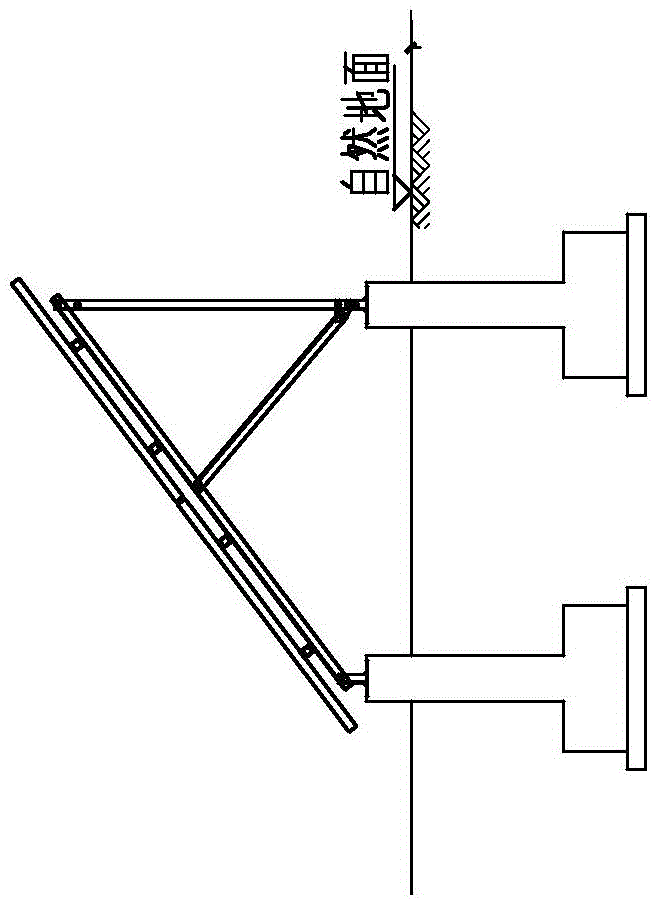
[0004] However, the reinforced concrete independent foundation also has very obvious defects: the construction period is long, the labor required is large, the amount of earthwork excavation and backfilling are large, a certain level of site is required, the damage to the environment is relatively large, and it is not conducive to the protection of environmental vegetation. and recovery
[0007] The main disadvantages of the spiral steel pile foundation are: the project cost is relatively high, and special construction machinery is required. The most important thing is that the horizontal bearing capacity of the foundation is closely related to the compactness of the soil layer. The spiral steel pile foundation requires the soil layer to have a certain Compactness, especially the shallow soil close to the surface should not be too loose or too weak, because if the shallow soil is loose, it cannot provide enough pile-soil interaction, and the horizontal displacement of the pile increases under the action of horizontal force, which is easy causing the stand to tilt sideways

Method used


Image

  • Anchor rod base structure with concrete block of photovoltaic module bracket and setting method
  • Anchor rod base structure with concrete block of photovoltaic module bracket and setting method
  • Anchor rod base structure with concrete block of photovoltaic module bracket and setting method

Examples


Embodiment Construction

[0030] Such as Figure 3-5 As shown, the present invention is an anchor rod foundation structure with concrete blocks for a photovoltaic module support, which includes a foundation 2 arranged on the ground 1, a photovoltaic support 3 is arranged on the foundation 2, and the foundation 2 includes an anchor rod 4 inserted into the ground, A concrete block 5 is sheathed on the outer side of the junction position between the top of the anchor rod 4 and the ground 1 .

[0031] Such as Figure 4 In the shown embodiment, the top of the anchor rod 4 is exposed to the concrete block 5, and the photovoltaic support 3 is connected to the exposed part of the top of the anchor rod. Its connection method can be bolt connection or other methods, and this connection method can be implemented by those skilled in the art.

[0032] Moreover, a tunnel 51 is reserved between the concrete block 5 and the anchor rod 4, and cement slurry can be poured into the tunnel.

[0033] Figure 4 The given...


PUM


Abstract

The invention discloses an anchor rod base structure with a concrete block of a photovoltaic module bracket and a setting method. The structure comprises a base arranged above the ground, a photovoltaic bracket is arranged on the base and the base comprises an anchor rod inserted into the ground, wherein the connection position between the top of the anchor rod and the ground is sleeved with a concrete block at the outer side. A novel steel anchor rod base with the concrete block is disclosed, suitable for most of the geology, capable of replacing the spiral steel pile base with potential safety hazard in the loose soil layer and is characterized in more reasonable in stress, better in security, wide in range of application and better in economy; the investment for building the photovoltaic power station on the ground is saved, the security is increased and the durability is strengthened.

Description

technical field [0001] The invention belongs to the field of solar photovoltaic power generation, and in particular relates to the basic structure of a photovoltaic module support in a photovoltaic power station. Background technique [0002] In the ground photovoltaic power station, the components used to realize photoelectric conversion are called photovoltaic modules. The photovoltaic bracket is a steel bracket used to support the photovoltaic module. The photovoltaic bracket is generally arranged in the open air on a wide area. At present, the foundation of photovoltaic support mostly adopts spiral steel pile foundation or traditional reinforced concrete independent foundation, and steel anchor rod foundation is often used in mountainous areas where rocks are exposed. [0003] Such as Figure 1a and Figure 1b As shown, the reinforced concrete independent foundation is one of the earliest forms of traditional photovoltaic support foundation, and it is also a foundation ...

Claims


Application Information

Patent Timeline
Patent Type & Authority Applications(China)
IPC IPC(8): E02D27/44
CPCE02D27/44
Inventor 杨菁李彦利吴真汪海燕
Owner NORTH CHINA POWER ENG
Learn More