
A kind of slag removal device for ladle

A ladle and slag sticking technology, applied in mechanical cleaning, manufacturing tools, metal processing equipment, etc., can solve the problems of easily broken bricks at the slag line, reduced ladle age, and labor intensity of workers, etc. Substantial features, improved package age, compact structure

Inactive Publication Date: 2016-08-10
SHANDONG IRON & STEEL CO LTD
View PDF4 Cites 0 Cited by
  • Summary
  • Abstract
  • Description
  • Claims
  • Application Information

AI Technical Summary

Problems solved by technology

[0002] The hot metal ladle has been used online, especially after pretreatment, and the slag line has a lot of sticky slag. In the prior art, the iron slag hook is generally removed by the crane hook. However, in the case of serious sticky slag in the hot metal ladle, Even if the molten iron ladle is hoisted with a crane, the iron slag is difficult to remove. At this time, only a pneumatic pick can be used to remove the sticky slag. On the one hand, the labor intensity of the workers is high; , it is easy to break the bricks at the slag line, resulting in a reduction in the age of the molten iron ladle, which is the deficiency of the existing technology

Method used


Image

  • A kind of slag removal device for ladle
  • A kind of slag removal device for ladle

Examples


Embodiment Construction

[0017] In order to clearly illustrate the technical features of the solution, the solution will be described below through a specific implementation mode combined with the accompanying drawings.

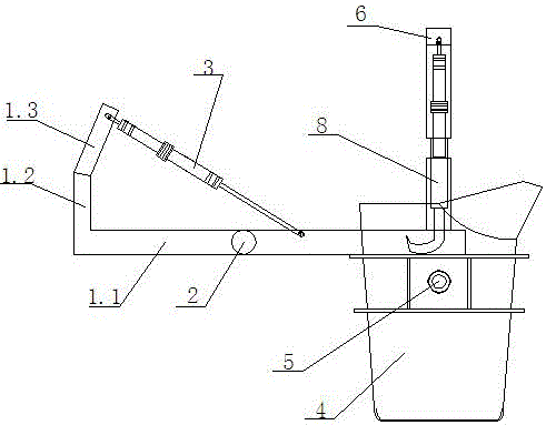
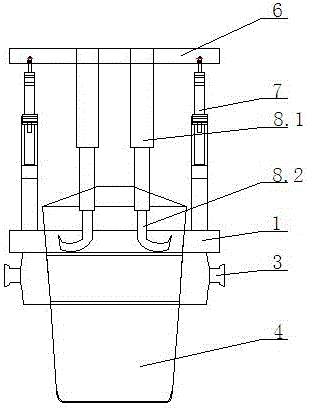
[0018] As can be seen from the accompanying drawings, a slag removing device for a ladle includes a compacting mechanism for compacting the ladle body 4 and a hook slag mechanism for removing sticky slag in the ladle 4, the compacting mechanism Including a rotating bracket 1, the rotating bracket 1 is composed of at least two arms fixedly connected, and the arms located at both ends of the rotating bracket 1 are respectively hingedly connected with the cylinder rod and the cylinder body of the rotating oil cylinder 3. When working, one end of the rotating bracket 1 The support arm is pressed on the trunnion seat 5 of the ladle 4, thereby the ladle 4 is fixed in the cleaning pit; in the present invention, the first support arm 1.1, the second support arm 1 and the second support arm of...


PUM


Abstract

The invention provides a technical scheme of a slag removing device for a ladle. The slag removing device comprises a pressing mechanism for tightly pressing a ladle body and a slag hooking mechanism for removing bonded slag in the ladle, wherein the pressing mechanism comprises rotatable supports, each rotatable support is formed by fixed connection of at least two sections of support arms, the support arms located at two ends of each rotatable support are hinged to and connected with a cylinder rod and a cylinder body of each rotatable oil cylinder respectively, and the support arm at one end of each rotatable support tightly presses a trunnion seat of the ladle during working; the slag hooking mechanism comprises a movable support driven by a movable support driving mechanism to move, and hooks for hooking and removing the bonded slag in the ladle are fixed at the lower part of the movable support. According to the slag removing device, the pressing mechanism presses and fixes the ladle in a cleaning pit, and meanwhile, movable oil cylinders are started to drive the hooks, so that the bonded slag in the ladle is removed.

Description

technical field [0001] The invention relates to the technical field of molten iron smelting, in particular to a slag removal device for ladles. Background technique [0002] The hot metal ladle has been used online, especially after pretreatment, and the slag line has a lot of sticky slag. In the prior art, the iron slag hook is generally removed by the crane hook. However, in the case of serious sticky slag in the hot metal ladle, Even if the molten iron ladle is hoisted with a crane, the iron slag is difficult to remove. At this time, only a pneumatic pick can be used to remove the sticky slag. On the one hand, the labor intensity of the workers is high; , it is easy to smash the bricks at the slag line position, causing the molten iron ladle age to reduce, which is the existing weak point of the prior art. Contents of the invention [0003] The technical problem to be solved by the present invention is to provide a technical solution for a ladle removal device for the ...

Claims


Application Information

Patent Timeline
Patent Type & Authority Patents(China)
IPC IPC(8): B22D43/00
CPCB22D43/005
Inventor 杜泽国江永波赵友虎尹卫平张世建楚志宝展军张贺全尹秀锦
Owner SHANDONG IRON & STEEL CO LTD
Learn More