
a filling valve

A filling valve and valve body technology, applied in the field of filling valves, can solve the problems of poor liquid seal and liquid leakage, and achieve the effect of simple installation and debugging

Active Publication Date: 2017-01-04
HANGZHOU ZHONGYA MACHINERY CO LTD
View PDF7 Cites 0 Cited by
  • Summary
  • Abstract
  • Description
  • Claims
  • Application Information

AI Technical Summary

Problems solved by technology

[0003] The technical problem to be solved by the present invention is to improve the existing filling valves that are not tightly sealed and have liquid leakage. The purpose is to provide a filling valve that is tightly sealed and has no liquid leakage. When the mounting part is peeled off, the installation and adjustment are easy, and there is no need for high-precision alignment operations

Method used


Image

  • a filling valve
  • a filling valve
  • a filling valve

Examples


Embodiment Construction

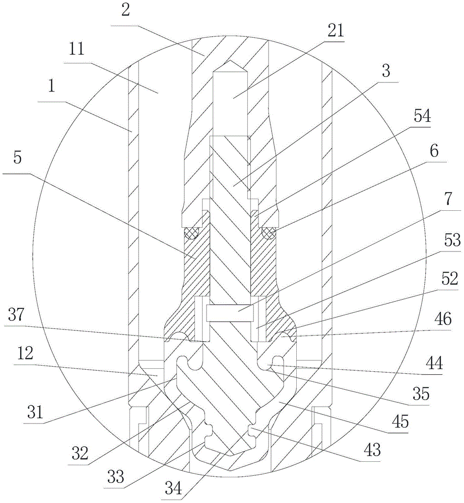
[0026] Such as Figures 1 to 11 Shown is an embodiment of a filling valve of the present invention, which includes a valve body 1 and a plugging rod 2. The valve body 1 has an inner cavity 11 that runs through the upper and lower ends of the valve body 1. The inner cavity 11 is a cylindrical cavity. The blocking rod 2 is located in the inner cavity 11, and the inner diameter of the valve body 1 gradually decreases at the bottom end of the inner cavity 11 to form a constriction 12, and the wall surface of the valve body 1 at the constriction 12 is a side structure of a circular platform; A sealing assembly consisting of a mounting part and a sealing sleeve 4 is installed. The sealing assembly is an axisymmetric structure as a whole. In the sealing assembly, the mounting part is wrapped in the sealing sleeve 4, and a hollow cavity is formed inside the sealing sleeve 4 to wrap the mounting part. 41. The bottom and sides of the sealing sleeve 4 are closed, and the top of the insta...


PUM


Abstract

The invention discloses a filling valve. The filling valve comprises a valve rod and a plug rod, the inner diameter of the valve body is reduced gradually to form a throat at the bottom end of the cavity, the plug rod enters the cavity from the top end of the valve body, a sealing component is arranged at the bottom end of the plug rod, the sealing component comprises a mounting part and a sealing sleeve which packages the mounting part, the sealing sleeve has a hollow cavity for holding the mounting part, a rod body which extends out of the sealing sleeve to connect with the plug rod is arranged at the top end of the mounting part, an opening through which the rod body passes is formed in the top wall body of the sealing sleeve, the mounting part has a support part, the outer diameter of the middle of the sealing sleeve is gradually reduced from the top to bottom to form a first reduced part, a first groove is formed in the side wall of the mounting part, a first flange is formed at the inner wall surface of the top wall body of the sealing sleeve, a second groove is formed in the top of the mounting part, and a second flange is formed at the inner wall of the sealing sleeve. The filling valve is tight in sealing, avoided from liquid drain, and easy and convenient to mount and regulate, and the filling valve does not need high-precision alignment operation.

Description

technical field [0001] The invention relates to a filling valve. Background technique [0002] The filling valve includes a valve body 1 and a plugging rod 2. The plugging rod 2 is located inside the valve body 1, and a liquid-tight connection is formed between the plugging rod 2 and the valve body 1 through surface-to-surface contact. Its structure is as follows: Figure 12 As shown, the connection between the valve body 1 and the plugging rod 2 is located at the end where the valve body 1 is provided with a discharge port; the liquid-tight connection structure described here is composed of a spherical surface on the blocking rod and a spherical surface inside the valve body. The radii of the two spherical surfaces are different, so a connection method of line contact is formed after contact. The spherical surfaces between two different radii contact each other to form a line connection, and thus meet the sealing requirements. The processing requirements for the spherical s...

Claims


Application Information

Patent Timeline
Patent Type & Authority Patents(China)
IPC IPC(8): F16K1/00F16K1/32F16K1/36F16K1/46B67C3/28
CPCB67C3/28F16K1/00F16K1/32F16K1/385F16K1/46F16K1/487
Inventor 史中伟吉永林金卫东
Owner HANGZHOU ZHONGYA MACHINERY CO LTD
Learn More