


Quick Research
Generate reliable direction feasibility study reports for your R&D in just a few steps.

Technical Q&A
Discover and master advanced knowledge NOW. Basics, ideas, possibilities, all at once.

Find Solutions
As an expert in R&D theories, this can generate solutions to your technical problems instantly.

Evaluate Feasibility
Analyze your overall solution with one click, know your potential R&D risks in advance.

Monitor Landscape
Get weekly tech updates, stay abreast of the latest tech innovations and key insights.
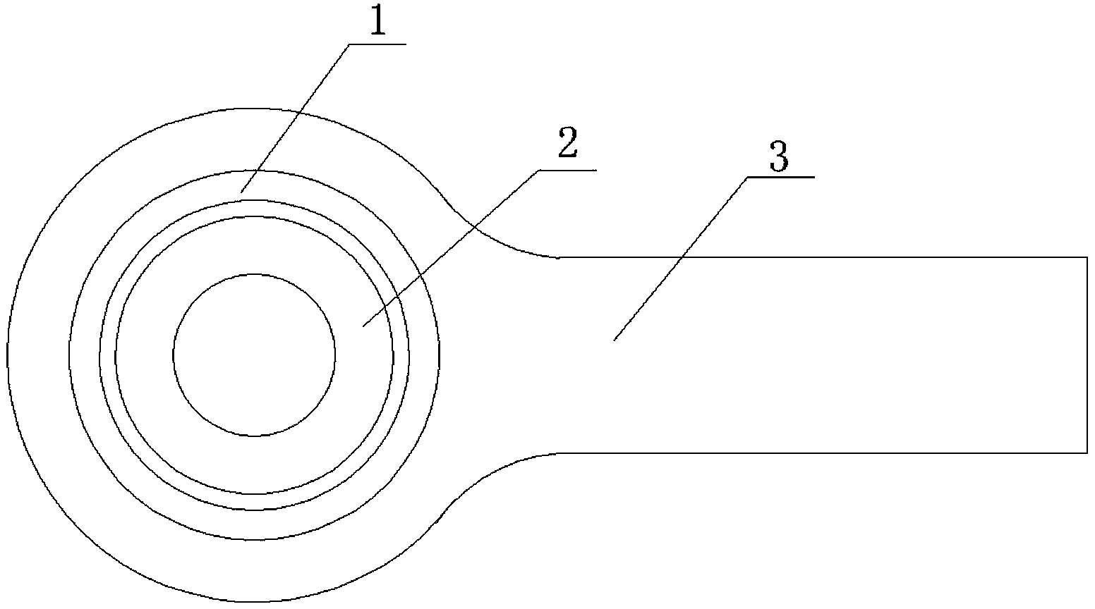
Rod end spherical plain bearing structure
A rod end joint bearing and tie rod technology, applied in the field of bearing manufacturing, can solve the problems of small radial force, thin outer ring wall thickness, inability to separate, etc., to increase axial bearing capacity, increase radial bearing capacity, The effect of reducing production costs
- Summary
- Abstract
- Description
- Claims
- Application Information
AI Technical Summary
Problems solved by technology
Method used
Image

Examples
Embodiment Construction
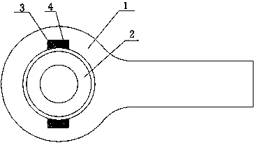
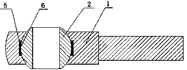
[0010] See figure 2 , a rod end joint bearing structure, which includes an outer ring 1 with a tie rod, an inner ring 2 is arranged inside the outer ring 1, a notch 3 is arranged on the inside of both ends of the outer ring 1, and the length of the notch 3 is the same as the outer diameter of the inner ring 2 Correspondingly, the width of the notch 3 corresponds to the thickness of the inner ring 2, the inner ring 2 is put into the outer ring 1 through the notch 3, the inner side of the outer ring 1 is spherical, the outer side of the inner ring 2 is spherical, and the outer ring 1 and the inner ring 2 Form a consistent spherical contact; there is a notch 3 on the inner side of both ends of the outer ring 1, and the inner ring 2 is inserted into the notch 3 transversely and then rotated to realize the cooperation between the inner spherical surface of the outer ring 1 and the outer spherical surface of the inner ring 2, forming a complete rod end joint The bearing, while ensu...
PUM
 Abstract
Description
Claims
Application Information
 - R&D Engineer
- R&D Manager
- IP Professional
- Industry Leading Data Capabilities
- Powerful AI technology
- Patent DNA Extraction
Browse by: Latest US Patents, China's latest patents, Technical Efficacy Thesaurus, Application Domain, Technology Topic, Popular Technical Reports.
© 2024 PatSnap. All rights reserved.Legal|Privacy policy|Modern Slavery Act Transparency Statement|Sitemap|About US| Contact US: help@patsnap.com