
Spinning method for bottle neck part of electrically conductive contact finger and matched spinning device

A technology of conductive contact finger and processing device, which is applied in the field of spinning processing, can solve the problems of reducing the processing cost of the conductive contact finger, cannot guarantee the wall thickness of the bottle neck of the conductive contact finger, etc., and achieves good flow capacity, convenient implementation, and simple operation. Effect

Active Publication Date: 2013-02-27
HENAN PINGGAO ELECTRIC +2
View PDF7 Cites 4 Cited by
  • Summary
  • Abstract
  • Description
  • Claims
  • Application Information

AI Technical Summary

Problems solved by technology

[0003] The purpose of the present invention is to provide a method for spinning the bottle neck of conductive contacts to solve the problem that conventional spinning cannot guarantee the thickness of the bottle neck of conductive contacts, thereby effectively reducing the processing cost of conductive contacts

Method used


Image

  • Spinning method for bottle neck part of electrically conductive contact finger and matched spinning device
  • Spinning method for bottle neck part of electrically conductive contact finger and matched spinning device
  • Spinning method for bottle neck part of electrically conductive contact finger and matched spinning device

Examples


Embodiment Construction

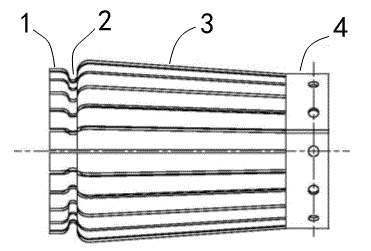
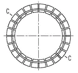
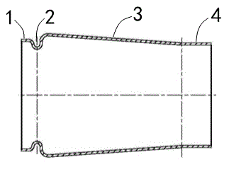
[0026] The conductive contact finger spinning processing method of the present invention is mainly to use the spinning wheel and the mandrel to form the bottleneck structure of the conductive contact finger, and at the same time, apply the conductive contact finger cylindrical blank along the axial direction of the mandrel. Axial pressure, thereby changing the material flow direction, ensures that the thinnest part of the conductive contact finger bottle neck is greater than 3 mm. In order to realize the spinning processing method, the present invention provides a spinning processing device dedicated to implementing the spinning processing method. The specific embodiment of the spinning processing device is as follows: Figure 4 to Figure 13 As shown, the processing device has a core mold for supporting and cooperating with the inner wall surface of the conductive contact finger cylindrical blank 60. and a mold core for supporting between the outer peripheral surface of the ma...


PUM

PropertyMeasurementUnit
tensile strengthaaaaaaaaaa

Abstract

The invention provides a spinning method for a bottle neck part of an electrically conductive contact finger. The spinning method is characterized in that while radial force is applied to a cylinder-shaped blank of the electrically conductive contact finger in the spinning process, axial pressure is applied to the cylinder-shaped blank of the electrically conductive contact finger in the axial direction of a core mold by utilizing a pressure loading mechanism, so that once the bottle neck part of the electrically conductive contact finger is stretched to be thinned under the action of the radial pressure of a spinning wheel, the axial pressure applied to the cylinder-shaped blank of the electrically conductive contact finger can push material to flow towards the thinned part of the bottle neck part in real time to timely supplement the stretched part, thereby preventing the bottle neck part of the electrically conductive contact finger from being stretched to be thinned. The spinning technology is simple to operate, is very convenient to implement and effectively guarantees the wall thickness of the bottle neck part of the electrically conductive contact finger in the spinning process, thereby guaranteeing that the electrically conductive contact finger manufactured by adopting the spinning technology has high flow capacity and satisfies the requirement of a megavolt power transmission and transformation line for an effective area of a through-flow cross section of the electrically conductive contact finger of a bypass isolating switch, and laying a solid foundation for smooth passing of 6300A of current.

Description

technical field [0001] The invention belongs to the technical field of spinning processing, and more precisely relates to a spinning processing method for the bottle neck of an UHV conductive contact finger and a spinning processing device specially used for implementing the method. Background technique [0002] With the continuous development and expansion of the national power market, UHV and high-current power transmission and transformation products have become the leading products in the power market, and the demand for million-volt series products continues to increase. In particular, the bypass isolating switch plays an important role in increasing the transmission power and maintaining the stability of the line in the million-volt power transmission line, and the conductive contact finger is a key part of the bypass isolating switch, and its current capacity is required to reach 6300A . The conductive contact finger of this bypass isolating switch is mainly made of ...

Claims


Application Information

Patent Timeline
Patent Type & Authority Applications(China)
IPC IPC(8): B21D22/16
Inventor 李宇鹏胡延涛孙玉洲侯亚峰郑晓春张任
Owner HENAN PINGGAO ELECTRIC
Learn More