
Broadband microstrip antenna and antenna array

A wideband, patch antenna technology, applied in antenna arrays, stripline feed arrays, antenna arrays that are powered independently, etc., can solve the problem of low directivity and achieve the effect of improving directivity

Inactive Publication Date: 2015-02-25
NUCTECH CO LTD +1
View PDF4 Cites 8 Cited by
  • Summary
  • Abstract
  • Description
  • Claims
  • Application Information

AI Technical Summary

Problems solved by technology

However, in view of the directionality requirement proposed in this paper, it is not common to expand the frequency band and have a strong directionality technology. In the general method of extending the frequency band, the dielectric board slotting or parasitic patch technology is often used. These technologies It can only solve the bandwidth requirements of the antenna, and its directivity is low

Method used


Image

  • Broadband microstrip antenna and antenna array
  • Broadband microstrip antenna and antenna array
  • Broadband microstrip antenna and antenna array

Examples


Embodiment Construction

[0036] Specific embodiments of the present invention will be described in detail below, and it should be noted that the embodiments described here are only for illustration, not for limiting the present invention. In the following description, numerous specific details are set forth in order to provide a thorough understanding of the present invention. It will be apparent, however, to one of ordinary skill in the art that these specific details need not be employed to practice the present invention. In other instances, well-known circuits, materials or methods have not been described in detail in order to avoid obscuring the present invention.

[0037] Throughout this specification, reference to "one embodiment," "an embodiment," "an example," or "example" means that a particular feature, structure, or characteristic described in connection with the embodiment or example is included in the present invention. In at least one embodiment. Thus, appearances of the phrases "in on...


PUM


Abstract

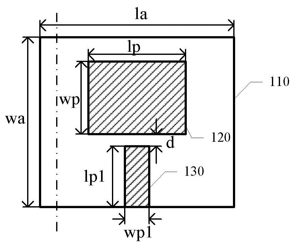
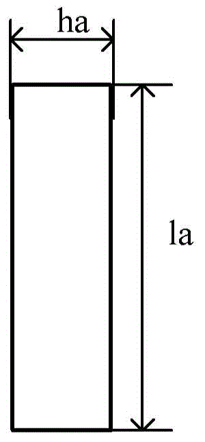
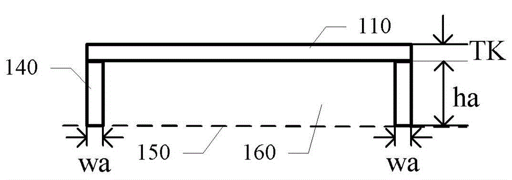
There is provided a wideband patch antenna and an antenna array. The antenna includes a dielectric substrate of a rectangle shape, a radiation patch formed on a top surface of the dielectric substrate, a coupling patch formed on the top surface of the dielectric substrate and extending from a side of the dielectric substrate to a position from the radiation patch by a distance, a metal support arranged on the lower surface of the dielectric substrate and extending from the edge of the lower surface of the dielectric substrate downward to the ground, a layer of air having a predetermined thickness being formed between the lower surface of the dielectric substrate and the ground. According to the embodiments, it is possible to improve the directivity of the wideband microstrip antenna while maintaining its small size.

Description

technical field [0001] The present application relates to microstrip antennas, in particular to the technical field of broadband antennas. Background technique [0002] In millimeter-wave holographic imaging technology, in order to obtain a three-dimensional image of the measured target, it is necessary to obtain complete data information through frequency scanning with a certain bandwidth. In the scanning system, the transceiver antenna is located at the forefront, responsible for transmitting signals to the object under test and receiving the signal reflected from the object under test. The system integrated transceiver antenna has the following requirements: (1) Small size, easy to integrate with ; (2) Strong directivity, the direction of the main beam is facing the measured object; (3) Wide frequency band, meeting the system's requirements for frequency bandwidth. [0003] In the system integration, there are a series of requirements for the scanning transceiver antenna...

Claims


Application Information

Patent Timeline
Patent Type & Authority Applications(China)
IPC IPC(8): H01Q9/04H01Q13/08H01Q1/52H01Q21/24
CPCH01Q9/0457H01Q9/045G03H5/00H01Q21/08H01Q5/378H01Q1/525H01Q13/02H01Q21/0081H01Q21/065H01Q1/422H01Q1/38H01Q1/52H01Q9/0407H01Q1/50
Inventor 赵自然陈志强李元景吴万龙刘以农杨洁青刘文国桑斌郑磊
Owner NUCTECH CO LTD
Learn More