
Energy accumulation tripping mechanism of breaker operating mechanism

A technology of operating mechanism and tripping mechanism, applied in the direction of protection switch operation/release mechanism, etc., can solve the problems of unreliable operation, inconvenient manufacturing, inability to meet the requirements of mechanization and automation, etc.

Active Publication Date: 2015-02-25
PINGGAO GRP +1
View PDF3 Cites 5 Cited by
  • Summary
  • Abstract
  • Description
  • Claims
  • Application Information

AI Technical Summary

Problems solved by technology

In the prior art, there are methods of immediately braking the motor, which mainly include two types: one is to manually cut off the power supply of the motor, and the other is to control the disconnection of the power supply through the mechanical transmission mechanism on the operating mechanism. However, in these two methods , the first method is often difficult to complete in an accurate specific time, and at the same time it is troublesome to rely on manual control by the staff, which cannot meet the needs of mechanization and automation. The second method can directly turn off the power supply through mechanical transmission within a specific time , but when this method is adopted, the machining accuracy of the energy storage mechanism is high, it is very inconvenient to manufacture, the production cost is high, and the problem of unreliable operation and poor stability often occurs due to the motion inertia of the motor

Method used


Image

  • Energy accumulation tripping mechanism of breaker operating mechanism
  • Energy accumulation tripping mechanism of breaker operating mechanism
  • Energy accumulation tripping mechanism of breaker operating mechanism

Examples


Embodiment Construction

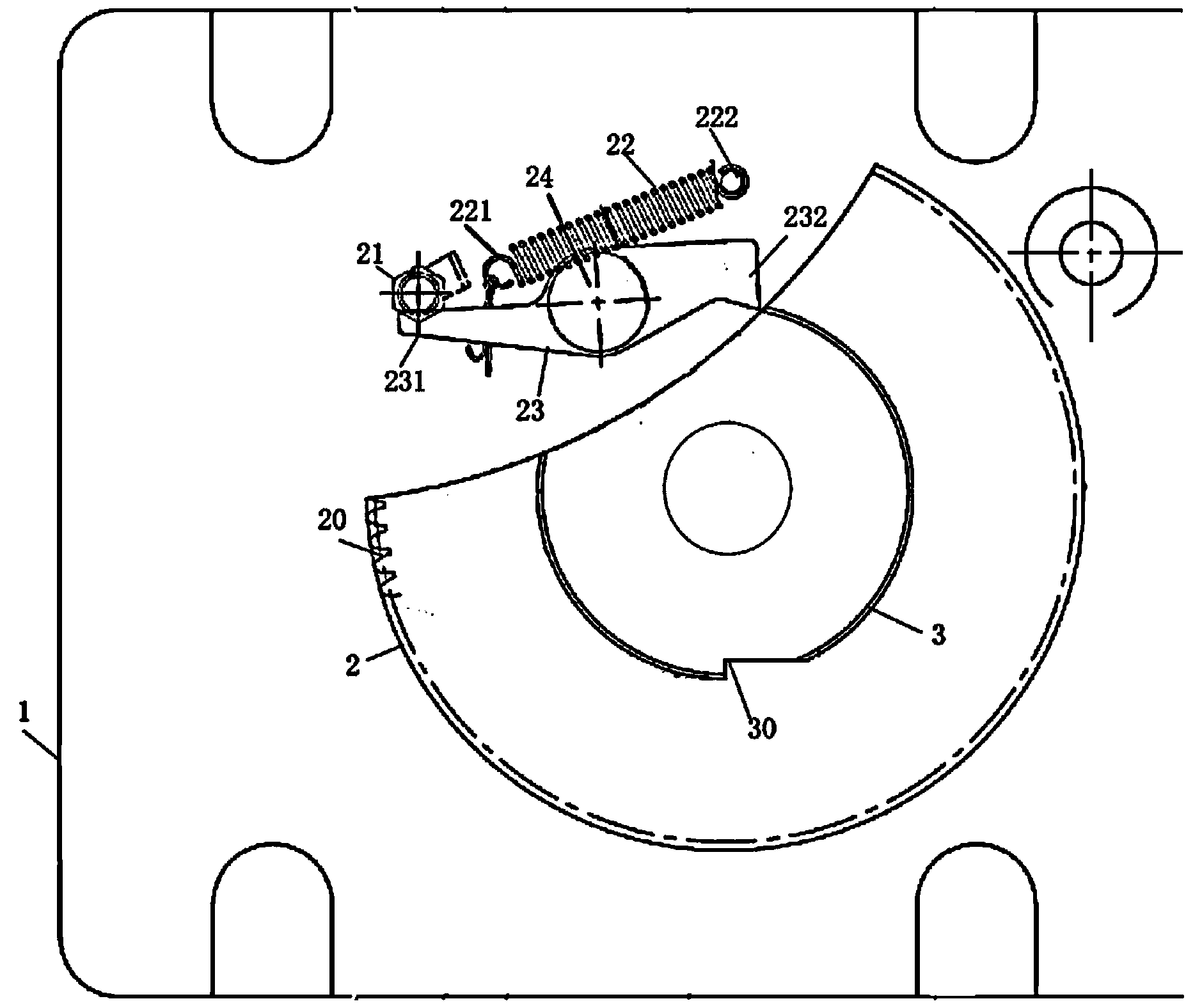
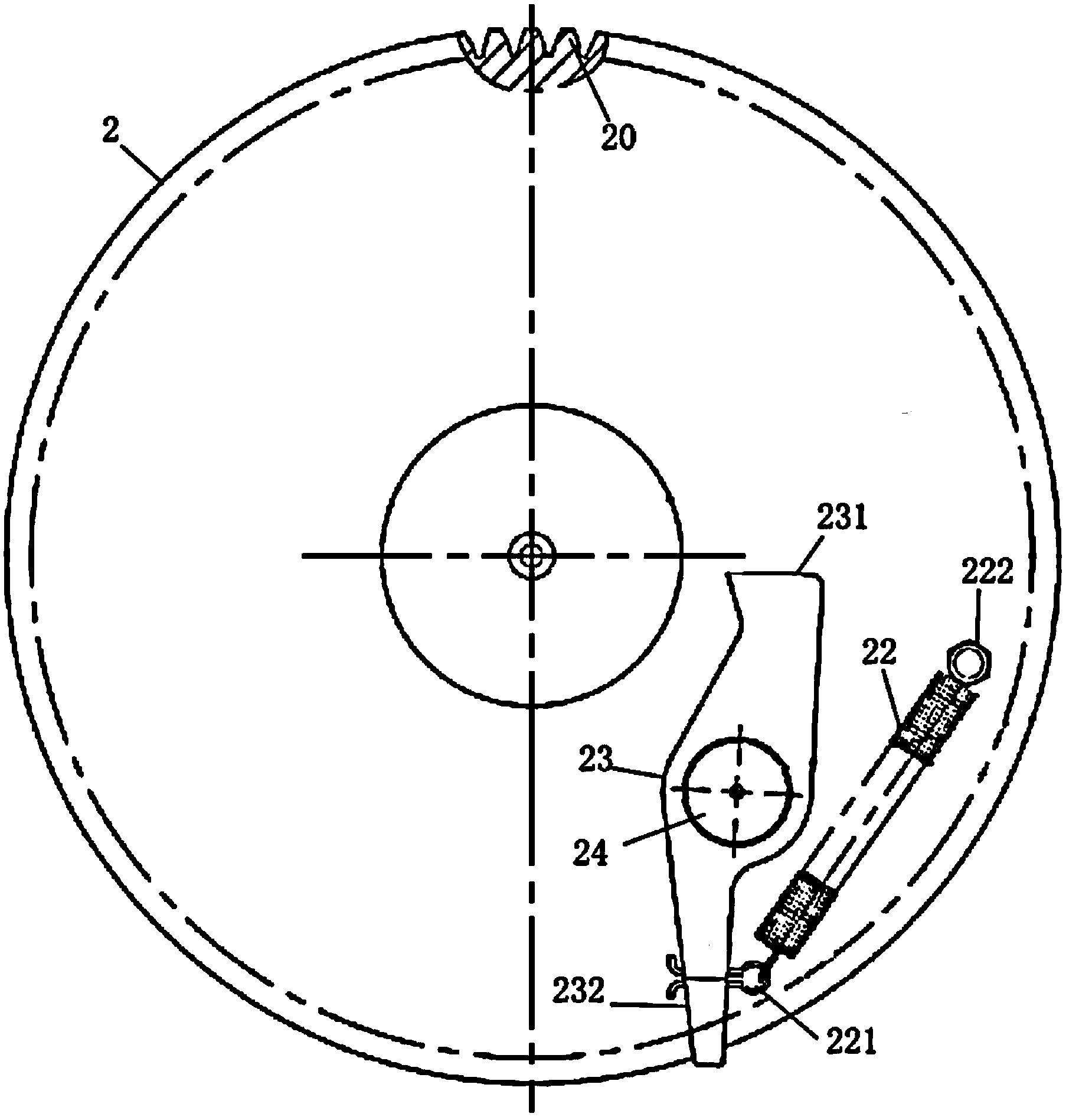
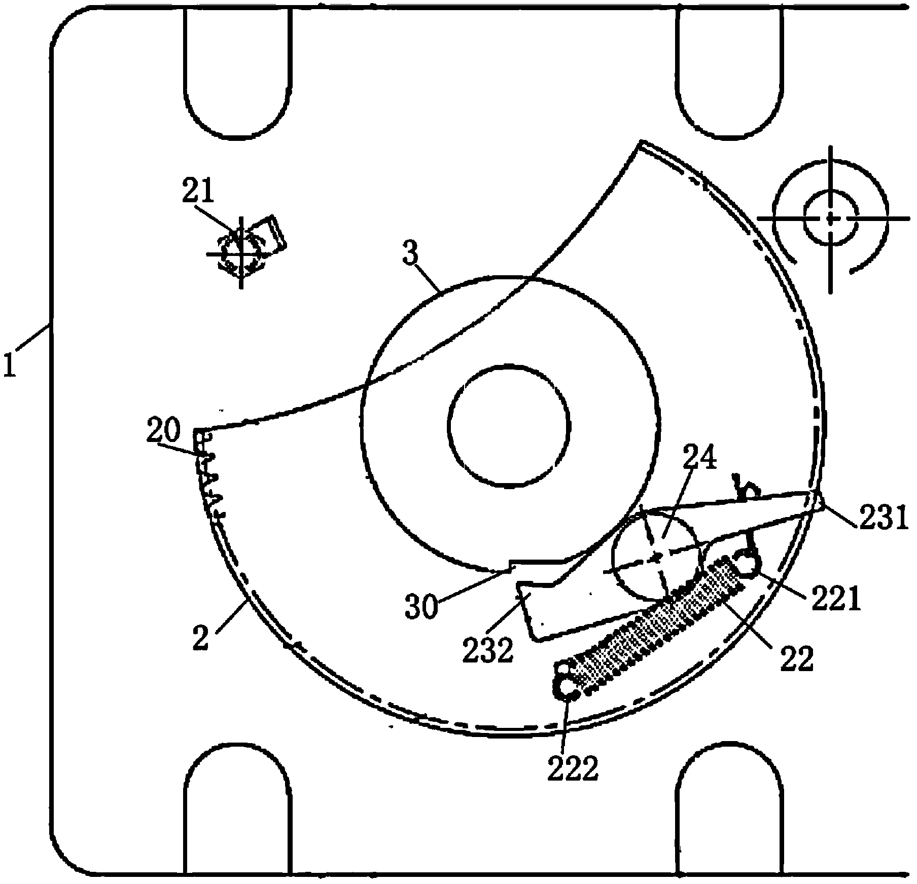
[0016] An embodiment of a circuit breaker operating mechanism energy storage tripping mechanism of the present invention: as Figure 1-6 As shown, it includes a fixed base 1, the fixed base 1 is provided with a motor and a power input shaft and an energy storage shaft 4 connected to the output end of the motor, the power input shaft transmits torque to the energy storage shaft 4, and the energy storage shaft The end of 4 is provided with the energy storage crank arm 5 that is connected with the energy storage spring and is used for energy storage, and the power input shaft and the energy storage shaft 4 are coaxial and are assembled on the fixed base 1 around its axis, and the power input shaft and the energy storage shaft 4 are coaxial. The energy storage shaft 4 is perpendicular to the fixed base 1, and the power input shaft is coaxially fixed with a rotating disk 2. The outer peripheral edge of the rotating disk 2 is provided with gear teeth 20 for transmission connection wi...


PUM


Abstract

The invention provides an energy accumulation tripping mechanism of a breaker operating mechanism. The energy accumulation tripping mechanism comprises a fixed base, a power input shaft and an energy accumulation shaft, and the power input shaft and the energy accumulation shaft are arranged on the fixed base and are coaxially assembled on the fixed base in the manner of mutually rotating around the axis of the power input shaft and the energy accumulation shaft. A transmission lever is hinged to the power input shaft in an eccentric mode, a stopping head is arranged at one end of the transmission lever, and a groove matched with the stopping head in a stopping mode is formed in the energy accumulation shaft. The power input shaft is further provided with an elastic piece which is connected with the transmission lever in order to enable the stopping head to abut against the energy accumulation shaft and enable the stopping head to slip into the groove when the transmission lever rotates to an energy accumulation starting position, and drives the energy accumulation shaft to rotate to accumulate energy. The fixed base is provided with a stopping block which is used for being matched with the transmission lever in a pushing mode and enabling the stopping head to be disengaged from the groove when the transmission lever rotates to an energy accumulation stopping position. The energy accumulation tripping mechanism can avoid the problems that because an energy accumulation system can not be disconnected immediately after energy accumulation is stopped, a motor continues driving a rotary disc to rotate, and accordingly the motor is burnt out or parts are damaged.

Description

technical field [0001] The invention relates to an energy storage tripping mechanism of an operating mechanism of a circuit breaker. Background technique [0002] In the field of high-voltage circuit breakers, due to the structural limitations of the circuit breaker operating mechanism, it is required that after the energy storage is completed, the motor should be able to brake immediately to stop the energy storage, so as to avoid damage to the parts caused by the continuous rotation of the motor. In the prior art, there are methods of immediately braking the motor, which mainly include two types: one is to manually cut off the power supply of the motor, and the other is to control the disconnection of the power supply through the mechanical transmission mechanism on the operating mechanism. However, in these two methods , the first method is often difficult to complete in an accurate specific time, and at the same time it is troublesome to rely on manual control by the sta...

Claims


Application Information

Patent Timeline
Patent Type & Authority Applications(China)
IPC IPC(8): H01H71/10
CPCH01H71/10H01H71/12
Inventor 肖超超张亚茹郭忠贺马志军姜冠玉李绘超
Owner PINGGAO GRP
Learn More