
Urea solution tank filling assembly used for SCR system

A technology of SCR system and solution tank, which is applied in the field of SCR system, can solve the problems of tank body expansion, cumbersome assembly, easy to wrap the tank cover, etc., and achieve the effect of stable and reliable use and convenient assembly

Active Publication Date: 2015-02-25
KAILONG HIGH TECH
View PDF6 Cites 8 Cited by
  • Summary
  • Abstract
  • Description
  • Claims
  • Application Information

AI Technical Summary

Problems solved by technology

[0004] 1) The chain used to connect the tank cover is easy to wrap around the tank cover during the rotation of the tank cover, causing the tank cover to fail to continue to rotate normally;
[0005] 2) During use, the gas inside the tank will not be discharged, causing the tank to expand;
[0006] 3) The filling port is assembled from multiple parts, which is cumbersome to assemble
[0007] These above-mentioned shortcomings have seriously affected the stability and economy of the whole SCR system, and become a problem urgently to be solved by those skilled in the art

Method used


Image

  • Urea solution tank filling assembly used for SCR system
  • Urea solution tank filling assembly used for SCR system
  • Urea solution tank filling assembly used for SCR system

Examples


Embodiment 1

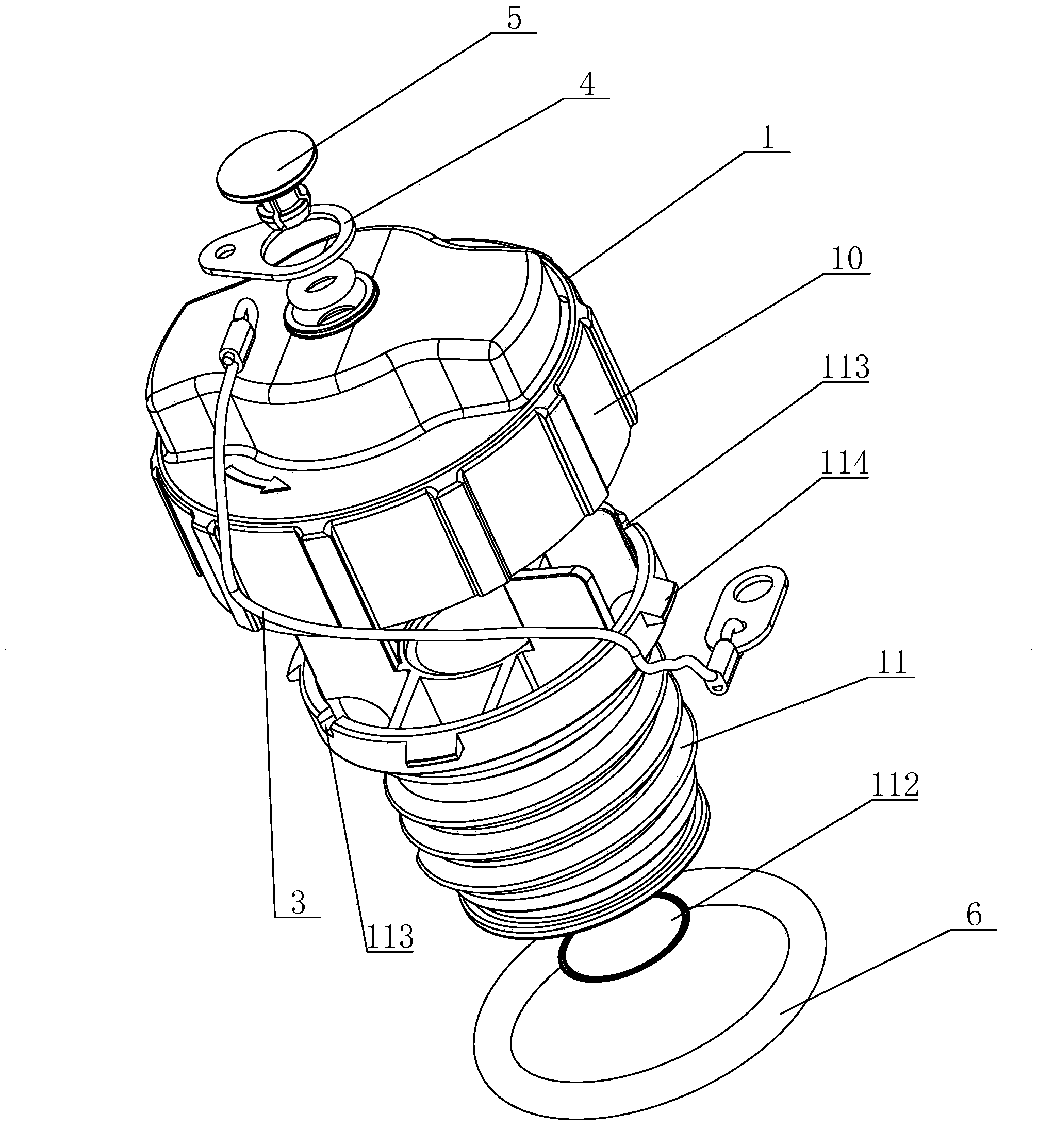
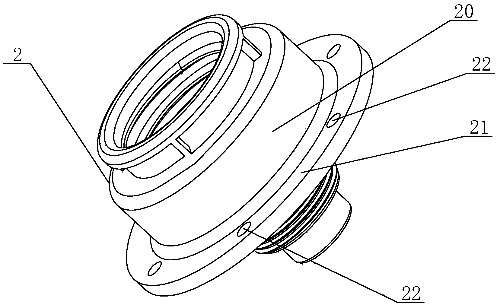
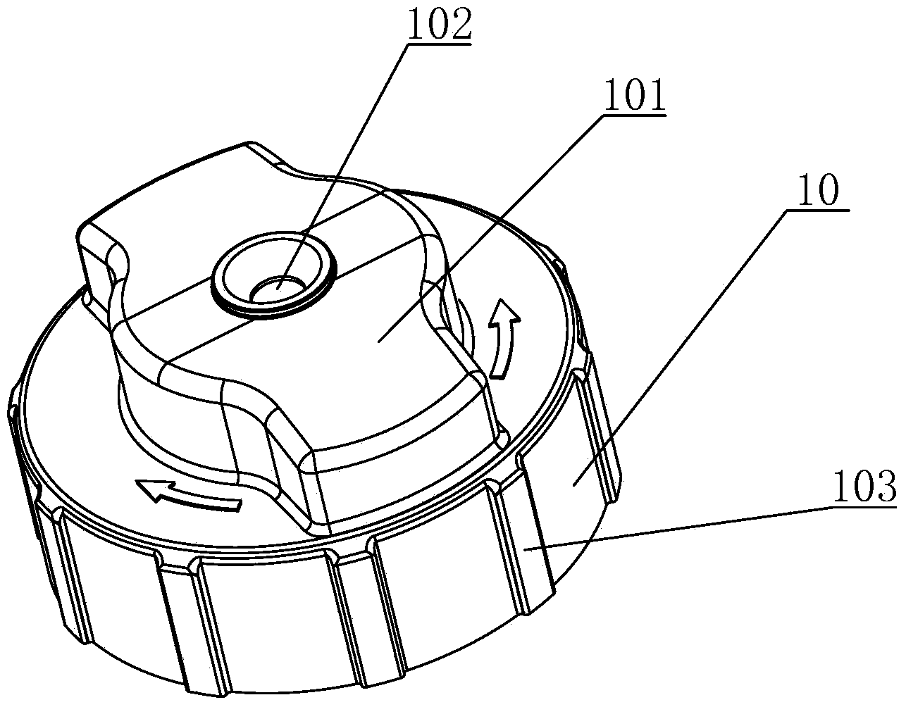
[0033] see Figure 1 to Figure 6 As shown, in this embodiment, a urea solution tank filling assembly for an SCR system includes a tank cover 1 and a filling port 2, and the tank cover 1 includes an upper outer cover 10 and a lower outer cover 11. The center of the lower outer cover 11 is provided with a vent chamber 110, and the bottom of the vent chamber 110 is provided with several vent holes 111, and the vent chamber 110 is provided with a vent membrane 112 above the vent holes 111, and the vent chamber 110 The top of the lower outer cover 11 is provided with several ventilation slots 113 and connected to the upper outer cover 10, the bottom of which is connected to the filling port 2, and the top of the lower outer cover 11 extends outwards with several chucks 114 , a plurality of slots are arranged on the top of the upper outer cover 10 in conjunction with the chuck 114 , and the chuck 114 is stuck in the slots to connect the lower outer cover 11 to the upper outer cover ...

Embodiment 2

[0037] see Figure 7 and Figure 8 As shown, the difference between this embodiment and Embodiment 1 is that an anti-loosening device is provided between the tank cover 1 and the filling port 2 , and the anti-loosening device includes an upper part of the filling port body 20 The anti-loosening teeth 23, cooperate with the anti-loosening teeth 23 to open a long anti-loosening bayonet 104 on the corresponding position of the upper outer cover 10, and the upper outer cover 10 is on the bottom of the anti-loosening bayonet 104 There is a raised part 105 extending downwards. When locking, the anti-loosening teeth 23 are stuck in the anti-loosening bayonet 104 to prevent the tank cover 1 from loosening. When opening the cover, rotate the upper outer cover 10, and the upper outer cover 10 will The protruding portion 105 on the cover 10 is deformed under force, so that the anti-loosening tooth 23 is separated from the anti-loosening bayonet 104 to realize unlocking.


PUM


Abstract

The invention discloses a urea solution tank filling assembly used for an SCR system. The urea solution tank filling assembly comprises a tank cover and a filling opening, the filling opening is formed in a urea solution tank, and a chain is connected between the filling opening and the tank cover. The tank cover comprises an upper outer cover body and a lower outer cover body, a ventilation cavity is formed in the center of the lower outer cover body, a plurality of ventilation holes are formed in the bottom of the ventilation cavity, ventilation film is arranged at the portion, located above the ventilation holes, of the ventilation cavity, a plurality of ventilation grooves are formed in the top of the lower outer cover body, the top of the lower outer cover body is connected with the interior of the upper outer cover body, the bottom of the lower outer cover body is connected with the filling opening, one end of the chain is connected to the top of the upper outer cover body in a rotatable mode, the other end of the chain is connected to the filling opening, and the filling opening is of an integrated structure. The urea solution tank filling assembly is convenient to assemble, and normal rotation of the tank cover can be guaranteed; in addition, expansion, caused by the fact that gas can not be effectively removed, of a tank body can be effectively prevented, and normal running of the system can be guaranteed.

Description

technical field [0001] The invention relates to an SCR system, in particular to a urea solution tank filling assembly for the SCR system. Background technique [0002] SCR (Selective Catalyst Reduction) for diesel engine selective catalytic conversion system refers to a catalytic reduction device installed in the exhaust system of diesel vehicles to catalytically reduce NOx in diesel engine emissions into N2 and O2, and urea aqueous solution is selected as the reducing agent. Urea aqueous solution is injected into the exhaust pipe upstream of the catalyst, and under the action of exhaust gas temperature and air flow, it is hydrolyzed into CO2 and ammonia, and ammonia acts as a reducing agent to reduce NOx into pollution-free nitrogen and water. [0003] The urea solution tank is an essential and important component in the SCR system. At present, the existing filling assembly of the urea solution tank used in the SCR system generally has the following disadvantages: [0004]...

Claims


Application Information

Patent Timeline
Patent Type & Authority Applications(China)
IPC IPC(8): F01N3/28
Inventor 臧志成
Owner KAILONG HIGH TECH
Learn More