
Hollow layering steam injecting system

A technology of layered steam injection and steam injection, which is applied in the fields of production fluids, wellbore/well components, earth-moving drilling, etc., and can solve the problems of steam leakage, easy steam leakage, affecting the accuracy of steam injection, etc.

Active Publication Date: 2015-02-25
PETROCHINA CO LTD
View PDF11 Cites 7 Cited by
  • Summary
  • Abstract
  • Description
  • Claims
  • Application Information

AI Technical Summary

Problems solved by technology

Secondly, due to the influence of the inclination angle during the drilling process, the steam distribution valve of the steam injection string is not completely vertical in the well, so there will be a locking phenomenon during the fishing process, resulting in that even if the fishing tool catches the steam injection The valve cannot be salvaged, which leads to the failure of salvage and the inability to adjust the steam injection volume of each layer
At the same time, since the upper and lower packers seal the annulus between the tubing and the casing, the positions of the two packers are fixed, and the thermal stress of the tubing between the upper and lower packers cannot be released during steam injection, which may easily cause deformation of the tubing and seriously In some cases, the packer will fail, causing steam leakage and affecting the accuracy of steam injection.
In addition, the wellhead required by the existing steam injection string is large in volume, high in the wellhead, and complex in structure, which affects the transmission efficiency on the one hand, and on the other hand, the steam is transported in the wellhead for a long distance, and the steam is easy to leak

Method used


Image

  • Hollow layering steam injecting system
  • Hollow layering steam injecting system
  • Hollow layering steam injecting system

Examples


Embodiment Construction

[0020] In order to have a clearer understanding of the technical features, purposes and effects of the present invention, the specific implementation manners of the present invention will now be described with reference to the accompanying drawings.

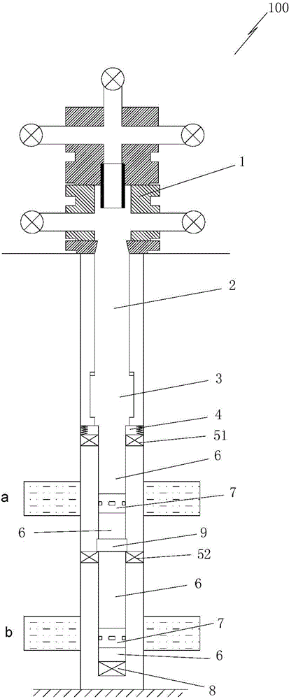
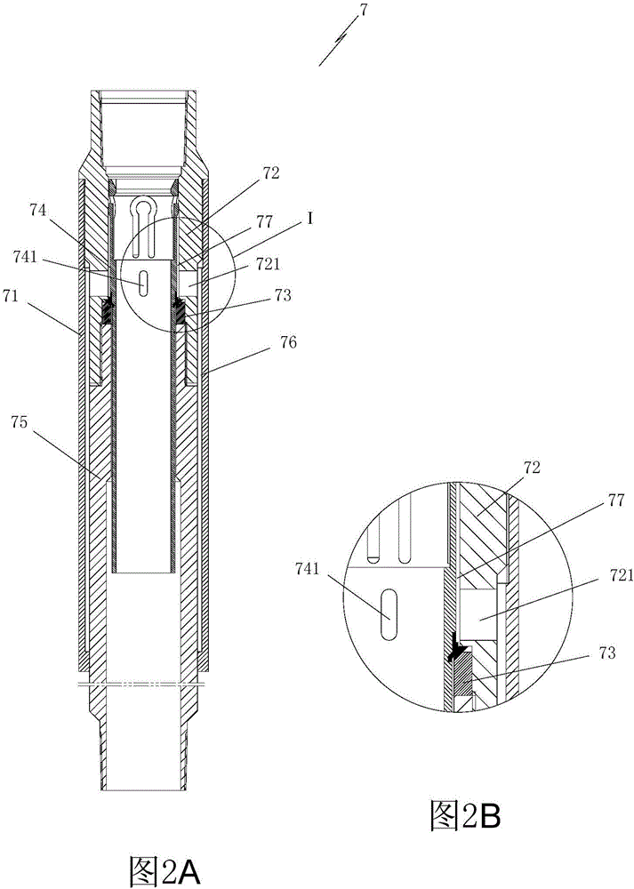
[0021] Such as figure 1 As shown, the present invention provides a hollow layered steam injection system 100, which is used to perform layered steam injection on two or more oil layers. In this embodiment, the case of two oil layers is used as an example for illustration . The steam injection system 100 includes a wellhead device 1. The wellhead device 1 uses snubbing steam to drive the wellhead. The wellhead is a prior art. The wellhead has a simple structure, and the transportation distance of steam in the wellhead is short, reducing the chance of steam leakage. The insulation oil pipe 2 is threadedly connected under the wellhead device. The insulation oil pipe adopts BG80H insulation oil pipe. Heat loss during transportation...


PUM


Abstract

The invention discloses a hollow layering steam injecting system. An heat preservation oil pipe is connected below a well head device; the lower end of the heat preservation oil pipe is connected with a telescopic pipe; the lower end of the telescopic pipe is connected with a steam distributing pipe column part; the steam distributing pipe column part comprises an anchor, an oil pipe, packers, an oil pipe releaser and a hollow steam injecting valve; the anchor is positioned at the uppermost end of the steam distributing pipe column part; the lower end of the telescopic pipe is connected with the anchor; in the steam distributing pipe column part, a top packer is arranged above a top oil layer, and is connected to the lower end of the anchor; a middle packer is arranged in a gap of adjacent two oil layers; the oil pipe, the hollow steam injecting valve and the oil pipe releaser are connected between adjacent two packers; and the lower end of the middle packer above a lowermost oil layer is connected with the oil pipe, the hollow steam injecting valve, the oil pipe and a plug. The hollow layering steam injecting system can preferably release thermal stress of a pipe column, is more accurate and effective in steam injecting effect, prevents the steam injecting valve from scaling to block a steam injecting channel, and increases the inner diameter of the pipe column for convenient dropping and fishing.

Description

technical field [0001] The invention relates to a layered steam flooding system used in heavy oil production, in particular to a hollow layered steam injection system. Background technique [0002] With the gradual increase of steam huff and puff cycle in heavy oil reservoirs in Liaohe Oilfield, the effect of steam huff and puff is getting worse gradually, and the requirement of changing the development mode is becoming more and more prominent. For multi-layer heavy oil reservoirs in Liaohe Oilfield, the large-scale application of layered steam flooding technology provides a guarantee for the production of crude oil in the block, but the pilot test and field construction show that the layered steam flooding technology has yet to In order to improve the performance of steam flooding in Class II and III heavy oil reservoirs (common classification standards in the field of heavy oil), it is necessary to improve and improve the supporting fishing technology urgently. mining eff...

Claims


Application Information

Patent Timeline
IPC IPC(8): E21B43/24
CPCE21B43/24
Inventor 张洪宝何传兴魏凯刘祖合赵树杰戚勇王巍杨冬梅杜晓雪
Owner PETROCHINA CO LTD
Learn More