
Sealing device and method for microcosmic displacement model injection and production opening

A sealing device and model technology, used in sealing/isolation, earth-moving drilling, wellbore/well components, etc., can solve the problem of shortening the service life of O-rings, leakage, easy changing positions of O-rings and glass surfaces, etc. problem, to achieve the effect of strong wear resistance and reliable sealing performance

Active Publication Date: 2015-02-25
PETROCHINA CO LTD
View PDF6 Cites 4 Cited by
  • Summary
  • Abstract
  • Description
  • Claims
  • Application Information

AI Technical Summary

Problems solved by technology

The commonly used sealing method is that the metal pipeline is sealed between the injection and production port of the glass model through an O-ring. This sealing method has the following disadvantages: First, when the injection medium is similar to CO 2 When the gas or liquid with corrosive properties is used, the service life of the O-ring will be severely shortened, and leakage may occur in the middle of the experiment, which cannot be predicted in advance; second, the position of the O-ring and the glass surface is easy to change under the action of pressure, resulting in leakage. The third is that under the action of pressure, the O-ring and the glass surface are not always perfectly attached together. If the temperature is too high or the pressure changes quickly, or the external confining pressure changes greatly, these factors will easily lead to leakage

Method used


Image

  • Sealing device and method for microcosmic displacement model injection and production opening
  • Sealing device and method for microcosmic displacement model injection and production opening
  • Sealing device and method for microcosmic displacement model injection and production opening

Examples


Embodiment Construction

[0027] In order to have a clearer understanding of the technical features, purposes and effects of the present invention, the specific implementation manners of the present invention will now be described with reference to the accompanying drawings.

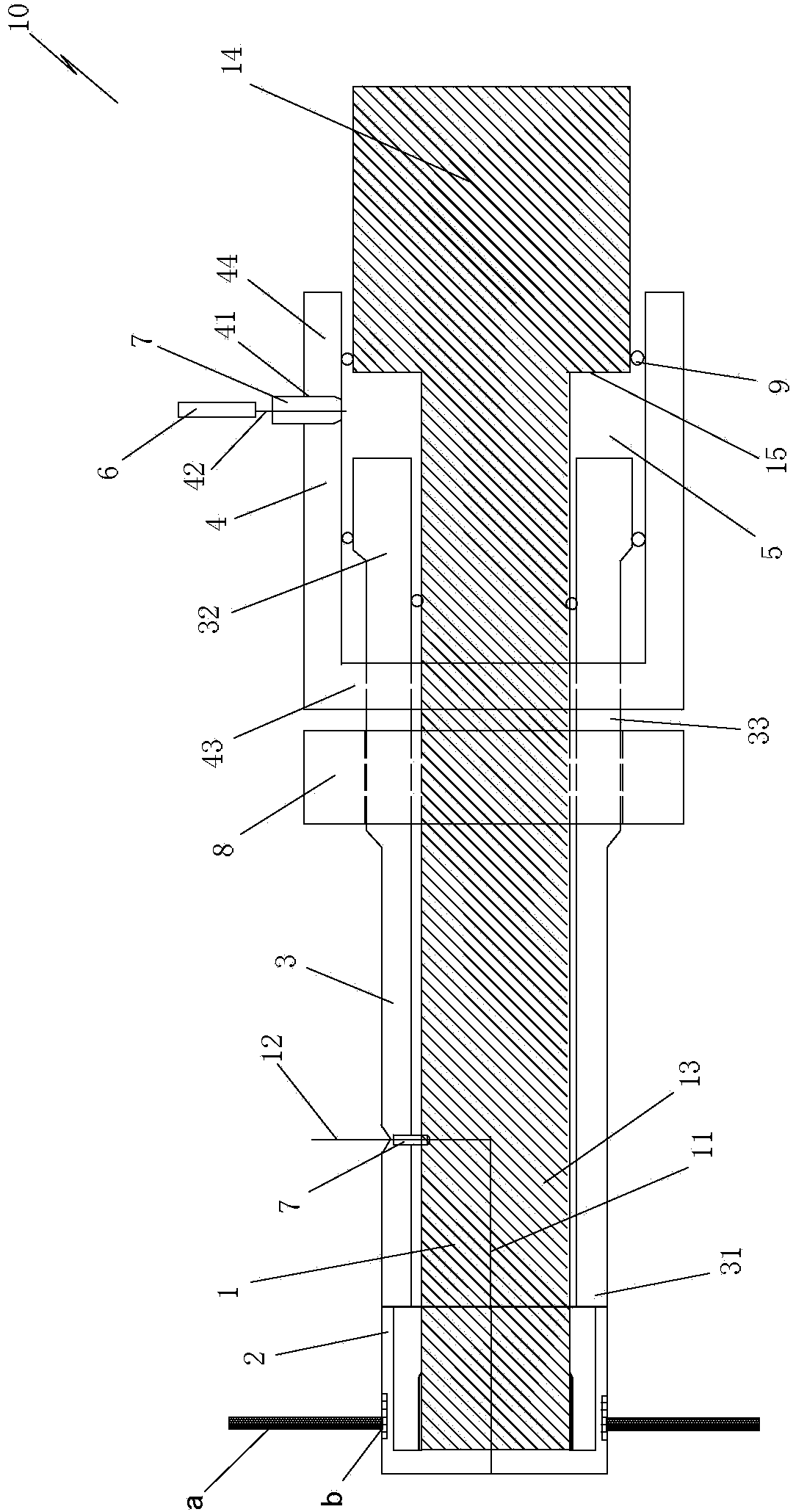
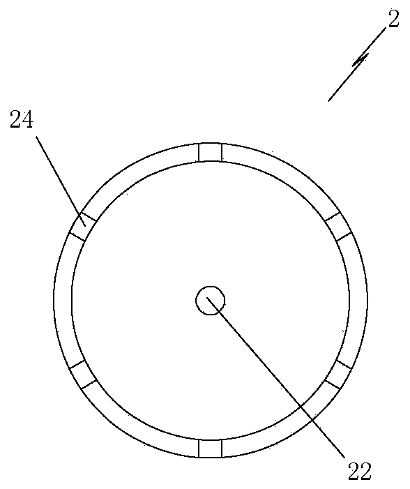
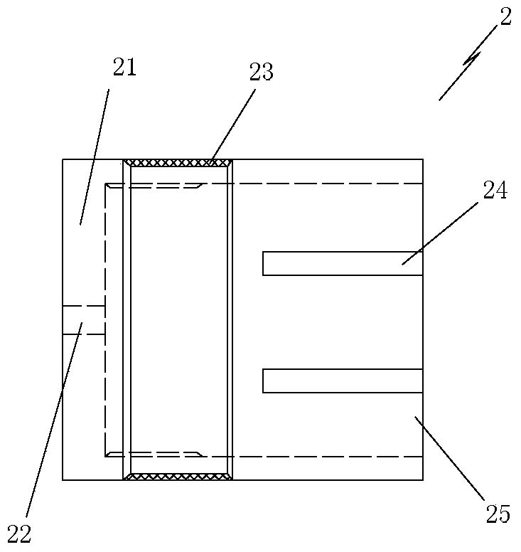
[0028] Such as figure 1 As shown, the present invention provides a sealing device 10 for injection and production ports of a microscopic displacement model. The microscopic glass etching model is commonly used in the microscopic displacement model, and the microscopic glass etching model a is adopted in this embodiment. The invention can also be applied to the injection-production opening sealing of one-dimensional / two-dimensional / three-dimensional cementation-displacement models. The sealing device 10 includes a main shaft 1. The main shaft 1 is composed of two sections of cylinders with different diameters. The main shaft 1 is provided with a liquid passage 11 inside, and the liquid passage 11 is connected with a fluid injectio...


PUM


Abstract

The invention discloses a sealing device and method for a microcosmic displacement model injection and production opening. The sealing device comprises a main shaft, wherein a liquid channel is formed inside the main shaft and connected with a fluid injection pipeline, the first end of the main shaft is a cylinder with a small diameter and in threaded connection with a sealing head which can generate radial deformation when bearing axial pressure, the second end of the main shaft is a cylinder with a large diameter, a platform shoulder portion is formed on the main shaft, an outer barrel is arranged outside the cylinder, with the small diameter, of the main shaft, the first end of the outer barrel abuts against the sealing head, a certain distance exists between the second end of the outer barrel and the platform shoulder portion of the main shaft, a sleeve type end cap is arranged outside the second end of the outer barrel and the second end of the main shaft in a sleeving mode, an annular closed space is formed among the inner wall of the sleeve type end cap, the second end of the outer barrel and the platform shoulder portion, and through holes are formed in the side wall of the sleeve type end cap and connected with a micro hydraulic pump through a pipeline. The sealing strength of the sealing device can be manually adjusted, the sealing device is reliable in sealing performance and high in anti-corrosion capacity and abrasion resistance, and sealing parts do not need to be regularly replaced.

Description

technical field [0001] The invention relates to a microscopic displacement technology in an oil-gas reservoir fluid seepage experiment, in particular to a sealing device and a sealing method for an injection-production port of a microscopic displacement model. Background technique [0002] In the technical research of enhanced oil recovery in oil and gas field development, no matter which method is used, the displacement medium and the displaced medium are involved. The feasibility of the method or technology of the medium. In order to obtain the oil and gas recovery factor, the microscopic displacement model is usually used for experiments. A commonly used microscopic displacement model is the microscopic glass etching model. The microscopic glass etching model can be used to quickly and intuitively evaluate the performance of the injection medium. inferior. The microscopic glass etching model is made by sintering two glass plates of the same size, and one of the glass pl...

Claims


Application Information

Patent Timeline
IPC IPC(8): E21B33/03
CPCE21B33/03
Inventor 张可马德胜李实秦积舜陈兴隆
Owner PETROCHINA CO LTD
Learn More