
A three-field axial variable magnification infrared optical system

An infrared optical system and optical system technology are applied in the field of three-field-of-view axial variable magnification infrared optical systems, which can solve the problems of excessive radial size and complex motion mechanism, reduce the difficulty of control and avoid the risk of pipe bending. Effect

Active Publication Date: 2017-06-06
LUOYANG INST OF ELECTRO OPTICAL EQUIP OF AVIC
View PDF3 Cites 0 Cited by
  • Summary
  • Abstract
  • Description
  • Claims
  • Application Information

AI Technical Summary

Problems solved by technology

[0004] The purpose of the present invention is to provide a three-field axial variable power infrared optical system to solve the problems of the existing infrared variable power optical system with too large radial size and complex movement mechanism

Method used


Image

  • A three-field axial variable magnification infrared optical system
  • A three-field axial variable magnification infrared optical system
  • A three-field axial variable magnification infrared optical system

Examples


Embodiment Construction

[0018] The present invention will be described in further detail below in conjunction with the accompanying drawings.

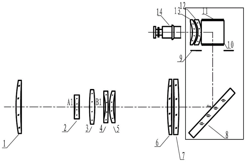
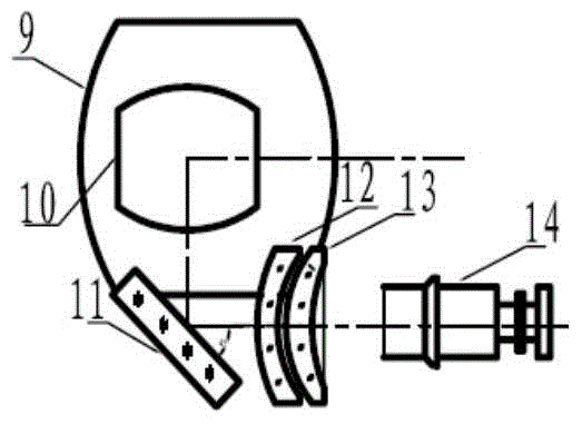
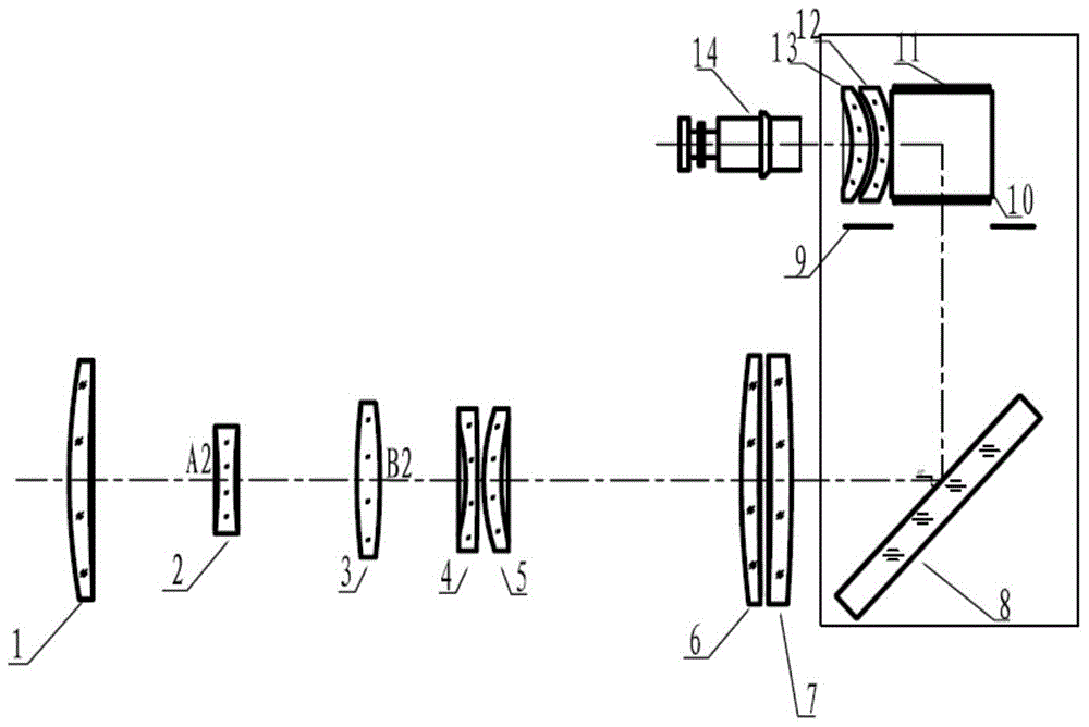
[0019] A three-field axial variable magnification infrared optical system, the optical system includes a front mirror group, a rear mirror group and a reflective mirror group for spatially deflecting the optical system; The objective lens 1, the zoom mirror 2, the compensation mirror 3, the first fixed mirror 4, the second fixed mirror 5, the third fixed mirror 6 and the fourth fixed mirror 7 are arranged on the axis, and the mirror group includes the first mirror arranged in sequence 8. The second reflector 10 and the third reflector 11, the rear mirror group includes the first converging mirror 12 and the second converging mirror 13 arranged on the same optical axis in sequence; the rear mirror group is on the reflection light path of the third reflector 11.

[0020] Based on the above technical solutions and in conjunction with the accompanying drawings, t...


PUM


Abstract

The invention relates to a three-view-filed axial zoom infrared optical system. The three-view-filed axial zoom infrared optical system comprises a front mirror set, a reflecting mirror set and a rear mirror set which are arranged in sequence. The front mirror set comprises an object mirror, a zoom mirror, a compensating mirror and four fixed mirrors, and the object mirror, the zoom mirror, the compensating mirror and the four fixed mirrors are coaxially arranged in sequence. The reflecting mirror set comprises three sequentially arranged reflecting mirrors. The rear mirror set comprises two convergent mirrors which are coaxially arranged in sequence. The rear mirror set is located on the reflecting optical path of the third reflecting mirror. According to the three-view-filed axial zoom infrared optical system, the three view fields can be changed just through axial movement of the zoom mirror and the compensating mirror, the compensating mirror only has two positions in the three-view-filed state, the compensating mirror also serves as a focusing mirror to compensate defocus caused by temperature, and therefore control difficulty is greatly lowered. The three fixed reflecting mirrors are adopted, an object image can be rotated through space bending, the problem that the direction of an adopted detector refrigerating machine is the same as the direction of a long edge is solved, the risk of pipe bending of the detector refrigerating machine is avoided, and the three-view-filed axial zoom infrared optical system is compact in structure, is provided with a simple movement mechanism and achieves miniaturization and low weight.

Description

technical field [0001] The invention relates to a three-field axial variable magnification infrared optical system, which belongs to the technical field of applied optics. Background technique [0002] At present, there are three zoom modes of the infrared zoom optical system: radial cut-in, rotary zoom and axial zoom. The radial cut-in method adopts radial switching of different zoom lens groups to realize the conversion of multiple fields of view. The rotary zoom mode adopts the coaxial rotation switching mode of different zoom lens groups to realize the conversion of multiple fields of view. The advantages of the above two methods are that the narrow field of view has the highest optical axis accuracy and the highest optical transmittance, but the disadvantages are that the radial size of the system is too large and the movement mechanism is complicated. The axial zoom method adopts the relative position movement of the zoom mirror and the compensation mirror to realize...

Claims


Application Information

Patent Timeline
Patent Type & Authority Patents(China)
IPC IPC(8): G02B27/00G02B7/04
CPCG02B7/04G02B27/00
Inventor 赵菲菲万敏潘晓东毛鑫
Owner LUOYANG INST OF ELECTRO OPTICAL EQUIP OF AVIC
Learn More