Analyzing method of gas discharge experiment under unconventional condition

A gas discharge and experimental analysis technology, applied in the direction of testing dielectric strength, etc., can solve problems such as inability to interpret air gap discharge signal information, backward test methods, and inability to accurately obtain the state of the discharge process.

Inactive Publication Date: 2015-02-18
HARBIN UNIV OF SCI & TECH
View PDF7 Cites 5 Cited by
  • Summary
  • Abstract
  • Description
  • Claims
  • Application Information

AI Technical Summary

Problems solved by technology

[0005] The purpose of the present invention is to solve the problem that the test means of the gas discharge process under unconventional conditions is backward, so that the state of the discharge process cannot be accurately obtained, and the information expressed by the air gap discharge signal cannot be interpreted. Gas discharge experimental analysis method

Method used


Image

  • Analyzing method of gas discharge experiment under unconventional condition
  • Analyzing method of gas discharge experiment under unconventional condition
  • Analyzing method of gas discharge experiment under unconventional condition

Examples


specific Embodiment approach 1

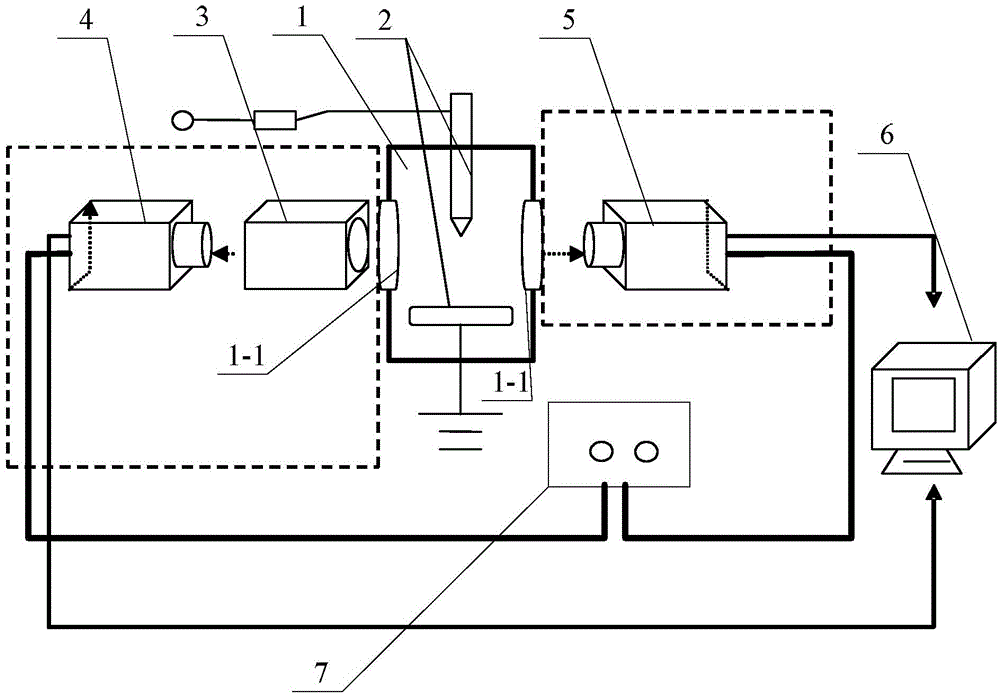
[0035] Specific implementation mode one: the following combination figure 1 Describe this embodiment, the gas discharge experimental analysis method under unconventional conditions described in this embodiment, it realizes based on the gas discharge experimental device under unconventional conditions, this experimental device includes airtight discharge chamber 1, bar plate copper electrode 2, monochromator 3. Optical image collector 4, discharge image collector 5 and computer 6,

[0036] The bar plate copper electrode 2 is arranged in the airtight discharge chamber 1, there is a gap between the head end of the bar part of the bar plate copper electrode 2 and the plate part, the plate part is connected to the power supply ground, and the end of the bar part is connected to the high voltage power supply through a resistor ;

[0037] Two opposite side walls of the airtight discharge chamber 1 are respectively provided with quartz glass windows 1-1, and the two opposite side wal...

specific Embodiment approach 2

[0058] Specific implementation mode two: this implementation mode will further describe the first embodiment mode, the particle density N e for:

[0059] N e = I 0 g + A + V + 2 ( 2 π m e kT ) 3 / 2 I + g 0 A 0 V 0 ...

specific Embodiment approach 3

[0083] Specific implementation mode three: the following combination figure 1 For illustration, this embodiment will further illustrate the first or second embodiment, the experimental device also includes a synchronizer 7,

[0084] The synchronization signal output terminal of the synchronizer 7 is connected to the synchronization signal input terminals of the optical image collector 4 and the discharge image collector 5 at the same time.


PUM


Abstract

The invention discloses an analyzing method of gas discharge experiment under an unconventional condition, belonging to the technical field of high-voltage and high-energy physical gas discharge. The analyzing method is used for solving the problem that information expressed by an air-gap discharge signal cannot be analyzed as the experimental means of the gas discharge process under the unconventional condition are laggard, and the discharge process state cannot be accurately obtained. The analyzing method comprises the following steps: firstly, obtaining spectral line intensity Inm when particles jump towards low energy level Em from high energy level En; obtaining a relative intensity ratio of two spectral lines, under the public low energy level, of the particles; establishing boltzmann distribution equation, and calculating according to the particle density ratio on the two energy levels Em and En of the same particles when the particles achieve thermodynamic equilibrium or local thermodynamic equilibrium to obtain a particle temperature T; and obtaining the particle density distribution by determining the spectral characteristic of a gas medium in a sealed discharge chamber according to the particle temperature T. The analyzing method disclosed by the invention is used for analyzing the gas discharge process.

Description

technical field [0001] The invention relates to a gas discharge experiment analysis method under unconventional conditions, and belongs to the technical field of high voltage and high energy physics gas discharge. Background technique [0002] The gas dielectric discharge characteristics under unconventional conditions are very different from the insulation characteristics under the usual DC, power frequency or long pulse. The reason is that the pulse width is similar to or smaller than the relaxation polarization time of the medium and the time scale of particle motion, especially under the narrow pulse conditions of nanosecond or even shorter pulses, the polarization history of the medium and the particle motion behavior have different performances. It will inevitably lead to changes in the insulation performance of the dielectric and its structure, and even many abnormal phenomena. This may be due to the differences in the transient electric field distribution between el...

Claims


Application Information

Patent Timeline
Patent Type & Authority Applications(China)
IPC IPC(8): G01R31/12
Inventor 郑殿春赵大伟郑秋平刘志勇陈亭杨仁旭
Owner HARBIN UNIV OF SCI & TECH
Why Eureka
Try Eureka