Condenser and refrigerator

A technology for condensers and refrigerators, applied in evaporators/condensers, refrigeration and liquefaction, coolers, etc., can solve the problem of rising exhaust pressure of compressors, increasing energy consumption of refrigerators, and reducing specific volume and flow rate, etc. problems, to achieve the effect of preventing the exhaust pressure from rising, reducing power consumption, and reducing material consumption

Inactive Publication Date: 2015-02-18
HEFEI HUALING CO LTD
View PDF5 Cites 2 Cited by
  • Summary
  • Abstract
  • Description
  • Claims
  • Application Information

AI Technical Summary

Problems solved by technology

[0002] At present, there are two kinds of natural convection condensers in refrigerators, one is hung on the back of the refrigerator, and the other is to use aluminum foil to paste galvanized steel pipes or Bondi tubes on the inside of the side panels of the refrigerator. Convective condenser, the pipeline flow path is a through pipeline, the interface of the pipeline does not change, figure 1 It shows the structural diagram of a common Bondi tube or galvanized steel pipe condenser. The outer diameter of the tube of this condenser 10 is generally 4 mm, and the wall thickness is generally 0.5 mm. From the phase zone to the subcooling zone, the specific volume and flow rate gradually decrease, while the flow section of the current condenser 10 does not change along the process. Although it can meet the heat dissipation requirements, it will lead to an increase in the resistance along the process. This will lead to an increase in the exhaust pressure of the compressor and an increase in power, thereby increasing the overall energy consumption of the refrigerator

Method used


Image

  • Condenser and refrigerator
  • Condenser and refrigerator
  • Condenser and refrigerator

Examples


Embodiment Construction

[0034] In order to understand the above-mentioned purpose, features and advantages of the present invention more clearly, the present invention will be further described in detail below in conjunction with the accompanying drawings and specific embodiments. It should be noted that, in the case of no conflict, the embodiments of the present application and the features in the embodiments can be combined with each other.

[0035] In the following description, many specific details are set forth in order to fully understand the present invention. However, the present invention can also be implemented in other ways than described here. Therefore, the protection scope of the present invention is not limited by the specific implementation disclosed below. Example limitations.

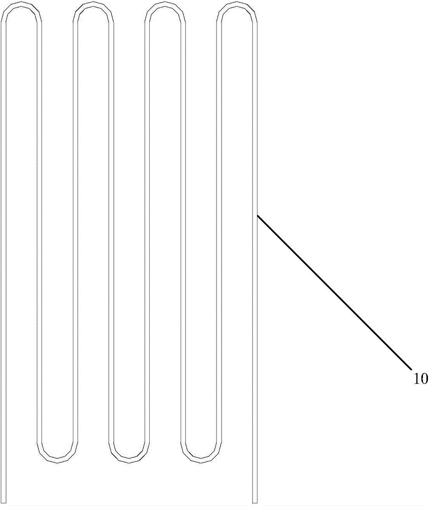
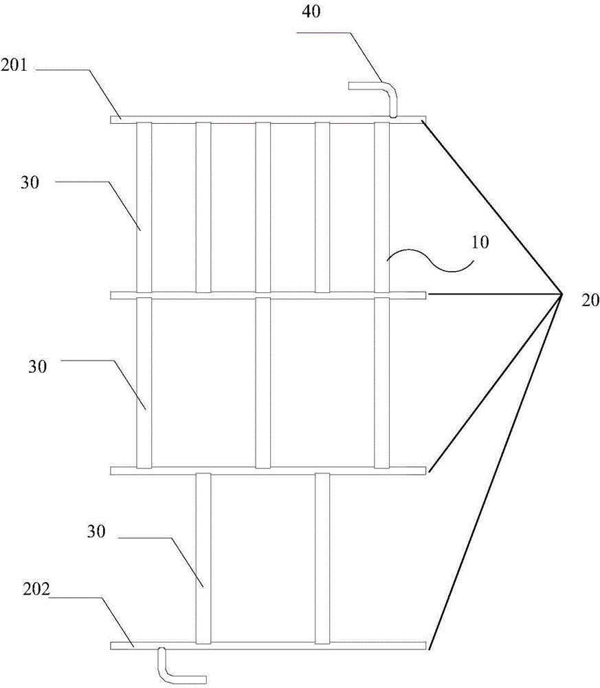
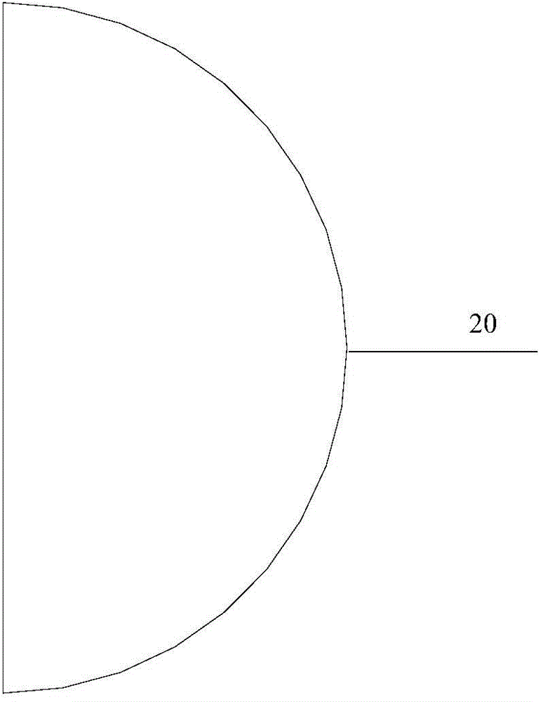
[0036] Refer below figure 2 and image 3 Condensers provided according to some embodiments of the present invention are described.

[0037] The present invention provides a condenser 10, comprising: a plu...


PUM


Abstract

The invention provides a condenser and a refrigerator. The condenser comprises a plurality of mutually parallel collector tubes and condenser pipes, wherein the condenser pipes are arranged between any two adjacent collector tubes, and the amount of the condenser pipes between any two adjacent collector tubes is different from that of condenser pipes between any other two adjacent collector tubes. Through the condenser and the refrigerator, the total circulation cross section of the condenser can be gradually decreased along with the decrease of the specific volume and flow rate of a refrigerating fluid on the basis of meeting the radiating requirement of the refrigerator, so that the material consumption of the condenser can be reduced, the on-way resistance of the refrigerating fluid in the condenser can also be reduced, and the power consumption of a compressor and the complete machine of the refrigerator is reduced.

Description

technical field [0001] The present invention relates to the technical field of condensers, and more specifically, to a condenser and a refrigerator. Background technique [0002] At present, there are two kinds of natural convection condensers in refrigerators, one is hung on the back of the refrigerator, and the other is to use aluminum foil to stick galvanized steel pipe or Bondi tube to the inside of the side panel of the refrigerator, but no matter what kind of natural convection Convective condenser, the pipeline flow path is a through pipeline, the interface of the pipeline does not change, figure 1 It shows the structural schematic diagram of a common Bondi tube or galvanized steel pipe condenser. The outer diameter of the tube of this condenser 10 is generally 4 mm, and the wall thickness is generally 0.5 mm. From the phase zone to the subcooling zone, its specific volume and flow rate gradually decrease, while the flow cross section of the current condenser 10 does...

Claims


Application Information

Patent Timeline
Patent Type & Authority Applications(China)
IPC IPC(8): F25B39/04F25D19/00
CPCF25B39/04F25B2500/05F25D19/00
Inventor 孟宪春史慧新
Owner HEFEI HUALING CO LTD
Why Eureka
Try Eureka