Self-protected under-pressure leakage plugging device and method for rushing to repair pipeline by using self-protected under-pressure leakage plugging device
A pressure plugging and self-protection technology, which is applied in the direction of pipe components, pipes/pipe joints/fittings, mechanical equipment, etc., can solve the problems that it is difficult to ensure the clamping force of the seal, the chain cannot be continuously adjusted, and the requirements for the working space are high. Achieve good sealing, convenient independent construction, and improve safety
- Summary
- Abstract
- Description
- Claims
- Application Information
AI Technical Summary
Problems solved by technology
Method used
Image
Examples
Embodiment 1
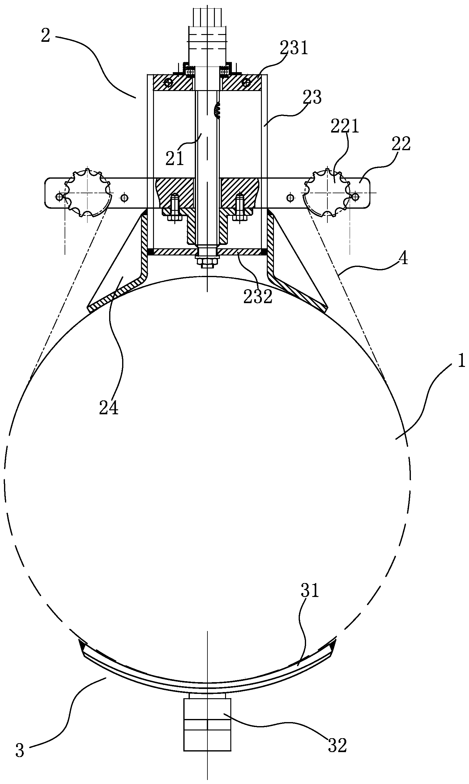
[0054] Such as figure 1 , 3 , 4, 5, 6, 7, 8, see figure 1, a self-protection plugging device with pressure in the present invention includes a fixture 2, a leak-stopping plate 3 and a chain 4, the fixture 2 tightens the leak-stopping plate 3 on the pipeline 1 through the chain 4, and the fixture 2 is tightened by a screw structure Tighten the chain 4, and the leak-stopping plate 3 utilizes the ball lock structure to reduce the pressure on the leakage of the pipeline 1 on the leak-stopping plate 3.
[0055] see image 3 The fixture 2 includes a screw rod 21, a lifting plate 22, a sprocket 221, a guide rail 23, an upper cross frame 231, a lower cross frame 232 and a base 24. The fixture 2 is clamped on the pipeline 1 through the base 24, and the base 24 is fixed by The lower cross frame 232, the longitudinal guide rail 23, and the frame formed by the upper cross frame 231, the upper cross frame 231 and the lower cross frame 232 are rotatably connected with the upper and lower...
Embodiment 2
[0074] Such as figure 2 As shown, the difference between the present embodiment 2 and the embodiment 1 is that a self-protection leak plugging device with pressure is used to repair the pipeline when the leak plugging plate 3 is rotated 180° in the circumferential direction and the space is relatively narrow, including the following steps:
[0075] A. Thread the valve 32 of the plugging plate 3 to the adapter 33, and screw down the bolt 34 in the middle of the adapter 33, so that the bolt 34 pushes down the sealing ball 321 to open the ball lock;
[0076] B. Place the middle part of the plugging plate 3 on the leakage of the pipeline 1;
[0077] C. Engage the two sets of fixtures 2 with the chain grooves of the plugging plate 3 at the same side of the leakage of the pipeline 1;
[0078] D, utilize the sprocket wheel 221 to fix the two ends of the chain 4, and the chain 4 fixes the leak-stopping plate through the chain groove of the leak-stopping plate 3;
[0079] E. Tighten...
PUM
 Abstract
Description
Claims
Application Information
 - R&D Engineer
- R&D Manager
- IP Professional
- Industry Leading Data Capabilities
- Powerful AI technology
- Patent DNA Extraction
Browse by: Latest US Patents, China's latest patents, Technical Efficacy Thesaurus, Application Domain, Technology Topic, Popular Technical Reports.
© 2024 PatSnap. All rights reserved.Legal|Privacy policy|Modern Slavery Act Transparency Statement|Sitemap|About US| Contact US: help@patsnap.com


