Method for replacing rubber isolation bearing

A replacement method and technology of vibration isolation rubber, applied in the direction of building maintenance, construction, building structure, etc., can solve the problems of inability to directly install the jack, insufficient vulcanization time, bulging, etc., so as to achieve a simple and fast introduction process and improve construction safety. , the effect of preventing natural rebound

Active Publication Date: 2015-02-18
YUNNAN QUAKESAFE SEISMIC ISOLATION TECH
View PDF4 Cites 9 Cited by
  • Summary
  • Abstract
  • Description
  • Claims
  • Application Information

AI Technical Summary

Problems solved by technology

[0004] However, if the vibration isolation bearing needs to be replaced during the construction process (for example, the temperature of the rubber during the vulcanization process does not reach the standard value, and the curing time is insufficient, resulting in quality problems such as rubber drumming of the vibration isolation bearing), or when using In the process, the damaged support needs to be replaced, and many problems will arise:
[0005] 1. Due to the limitations of the foundation, the design of the lower pier is small. When the upper pier is lifted, the jack cannot be directly installed on the lower pier, and the ground is far away from the upper pier, making it difficult to set up the layout
[0006] 2. Due to the gravity of the upper pier and the building, the support to be replaced may have certain compression deformation and horizontal displacement, so the bolt holes of the support to be replaced will be offset
The bolt holes of the new seismic isolation support cannot correspond to the bolt holes of the pier, and cannot be installed in place
[0007] 3. The support to be replaced is compressed under the load of the upper pier, and it will rebound when the upper pier is lifted to replace the support. Increasing the jacking amount of the upper pier will pose a greater threat to the building structure

Method used


Image

  • Method for replacing rubber isolation bearing
  • Method for replacing rubber isolation bearing
  • Method for replacing rubber isolation bearing

Examples


Embodiment Construction

[0037] Specific embodiments of the present invention will be described in detail below with reference to the accompanying drawings.

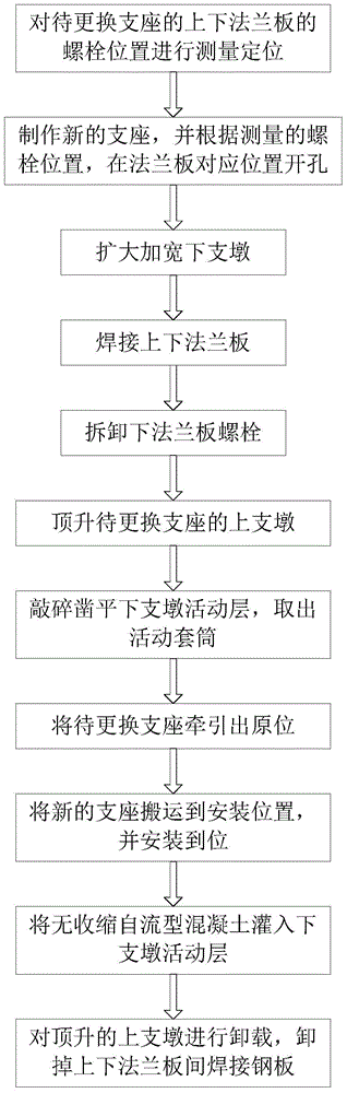
[0038] See figure 2 , which is a flow chart of an embodiment of the method for replacing a vibration-isolation rubber bearing of the present invention, including the following steps:

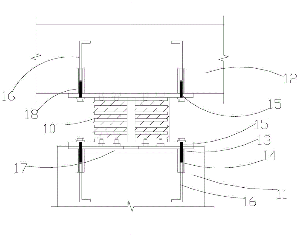
[0039] (1) Measure and locate the bolt positions of the upper and lower flange plates of the shock-isolation bearing to be replaced.

[0040] (2) Make a new shock-isolation support, and drill holes at the corresponding positions on the flange plate according to the measured bolt positions.

[0041] (3) Expand and widen the lower buttress.

[0042] (4) Weld the upper and lower flange plates of the shock-absorbing support with steel plates.

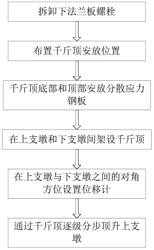
[0043] (5) Remove the flange plate bolts under the support.

[0044] (6) Lift the upper pier of the shock-isolation bearing to be replaced.

[0045] (7) Crush and chisel the movable layer of the lower pier, and take out t...


PUM


Abstract

The invention relates to a method for replacing a rubber isolation bearing. The method comprises the following steps of (1) enlarging a lower buttress; (2) measuring and positioning bolts of upper and lower flange plates of a rubber isolation bearing to be replaced; (3) manufacturing a new isolation bearing, and forming holes in corresponding positions of flange plates of the new isolation bearing according to the measured bolt positions; (4) welding the upper and lower flange plates of the bearing to be replaced; (5) taking out lower flange plate bolts of the isolation bearing to be replaced; (6) jacking an upper buttress of the isolation bearing to be replaced; (7) taking an embedded plate, knocking off a lower buttress movable layer and taking out a movable sleeve out; (8) dragging the isolation bearing to be replace out of the normal position; (9) prestressing the new isolation bearing, and welding the upper and lower flange plates; (10) carrying the new bearing to the installation position, and fixedly installing the new bearing; (11) pouring non-shrinkage automatic flow concrete into the lower buttress movable layer; (12) unloading the jacked upper buttress. According to the method, aims of safety, high efficiency, no damage to an upper structural layer and reduction of replacement cost can be fulfilled.

Description

technical field [0001] The invention relates to the technical field of building isolation, in particular to a method for replacing an isolation support. Background technique [0002] Based on the previous "rigid anti-seismic" building anti-seismic idea, the anti-seismic basically relies on increasing the resistance of the isolation structure to resist the huge earthquake damage. However, such an approach does not conform to modern construction requirements such as light weight, high strength, energy saving, environmental protection, and engineering economy, and such an approach cannot resist rare earthquakes with high intensity. The current structure adopts the idea of ​​"flexible anti-seismic" to alleviate the seismic response of the structure, which can not only ensure the safety of the structure, but also reduce the construction cost, save energy and protect the environment. "Flexible earthquake resistance" does not blindly adopt the idea of ​​"hard resistance" to ensure...

Claims


Application Information

Patent Timeline
Patent Type & Authority Applications(China)
IPC IPC(8): E04G23/02
Inventor 廖云昆龙云刚
Owner YUNNAN QUAKESAFE SEISMIC ISOLATION TECH
Why Eureka
Try Eureka