
Automatic material distributing mechanism and material distributing method thereof

A sorting mechanism and automatic technology, applied in the direction of conveyor objects, transportation and packaging, etc., can solve the problems of occupation, high labor cost, low production capacity, etc.

Active Publication Date: 2015-02-18
DONG GUAN TAISOL ELECTRONICS CO LTD
View PDF13 Cites 10 Cited by
  • Summary
  • Abstract
  • Description
  • Claims
  • Application Information

AI Technical Summary

Problems solved by technology

[0002] In the field of computer heat sinks, when assembling heat sinks and fans, many fixed installation parts such as springs and screws are needed, especially for products that require porous fixing, a large number of the above-mentioned fixed installation parts will be used, and At present, the material is divided manually in the assembly line, and the installation parts such as springs and screws are distributed to the required installation parts. This way, the labor cost is high, the production capacity is low, and the assembly line resources of the workshop are occupied. The irregular operation of the employees will also cause the oxidation of the surface of the material. , affecting the quality of the product

Method used


Image

  • Automatic material distributing mechanism and material distributing method thereof
  • Automatic material distributing mechanism and material distributing method thereof
  • Automatic material distributing mechanism and material distributing method thereof

Examples


Embodiment 1

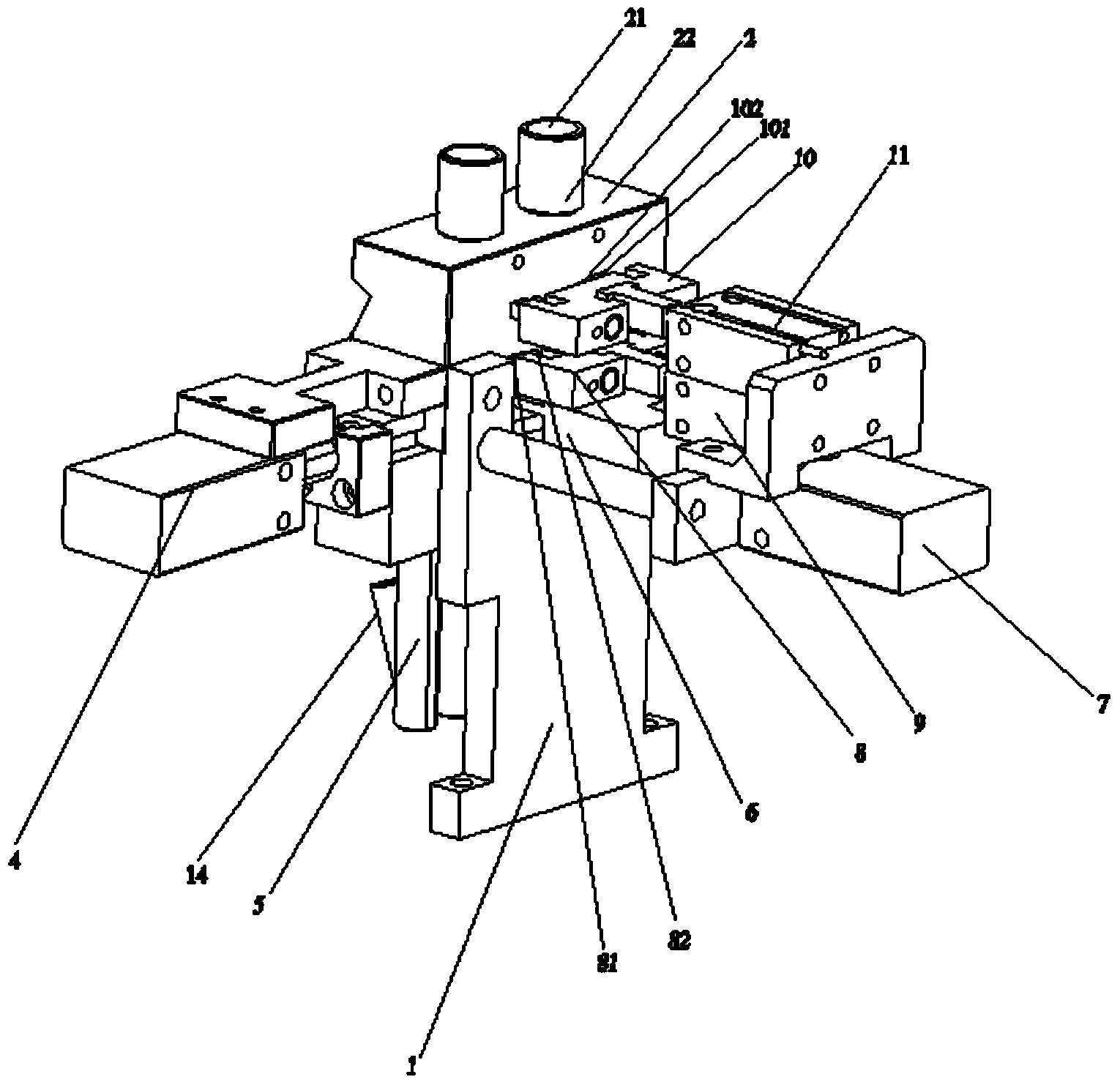
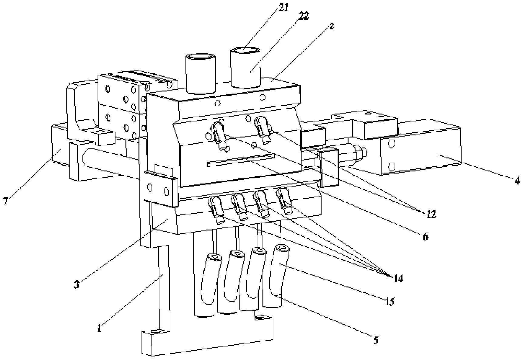
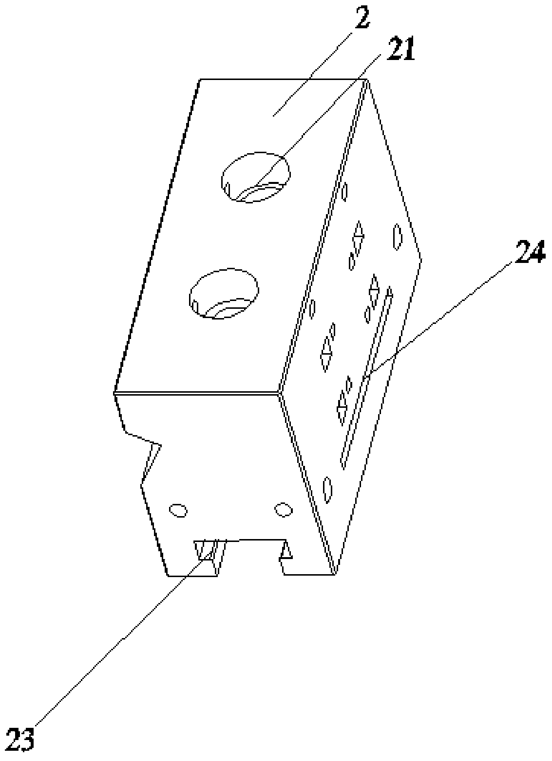
[0029] Such as Figure 1-4 As shown, an automatic feeding mechanism includes a support frame 1 and a feed block 2 fixed on the support frame 1. At least two feed openings 21 are opened on the top of the feed block 2. The feed block 2 is provided with a feed rail 22 communicating with the feed port 21, the bottom of the feed block 2 is provided with a chute 23, and a slider 3 is provided below the feed block 2, the The slider 3 is movably clamped on the sliding groove 23, the slider 3 is provided with at least four through holes 31, the slider 3 is driven by the first air cylinder 4, and the slider 3 is provided below There is a discharging track 5 communicating with the through hole 31, a discharging block 6 is arranged below the feeding rail 22, and the discharging block 6 is driven by the second cylinder 7, and the discharging block 6 is above A correction mechanism 8 extending into the feed rail 5 is provided, the correction mechanism 8 is driven by a third cylinder 9, and ...


PUM


Abstract

The invention relates to the technical field of automatic manufacturing devices and manufacturing methods, in particular to an automatic material distributing mechanism. The automatic material distributing mechanism comprises a supporting bracket, a feeding block fixedly arranged on the supporting bracket, a correcting mechanism and a material pressing mechanism, wherein at least two feed openings are formed in the top part of the feeding block; feeding tracks communicated with the feed openings are formed in the feeding block; a sliding groove is formed in the bottom part of the feeding block; a sliding block is arranged at the lower part of the feeding block, and is movably clamped on the sliding groove; at least four through holes are formed in the sliding block; the sliding block is driven by a first air cylinder; discharging tracks communicated with the through holes are formed in the lower part of the sliding block; a discharging block is arranged below the feeding tracks, and is driven by a second air cylinder. The invention further discloses a method for material distribution by adopting the automatic material distributing mechanism. Compared with the prior art, the automatic material distributing mechanism supplies fixed mounting parts for products required to be fixed by multiple holes, can convey multiple parts at a time, improves the production efficiency, and is high in automatic degree, simple in structure and convenient to operate.

Description

technical field [0001] The invention relates to the technical field of automatic processing devices and processing methods, in particular to an automatic material distribution mechanism and a material distribution method. Background technique [0002] In the field of computer heat sinks, when assembling heat sinks and fans, many fixed installation parts such as springs and screws are needed, especially for products that require porous fixing, a large number of the above-mentioned fixed installation parts will be used, and At present, the material is divided manually in the assembly line, and the installation parts such as springs and screws are distributed to the required installation parts. This way, the labor cost is high, the production capacity is low, and the assembly line resources of the workshop are occupied. The irregular operation of the employees will also cause the oxidation of the surface of the material. , affecting the quality of the product. [0003] Therefo...

Claims


Application Information

Patent Timeline
Patent Type & Authority Applications(China)
IPC IPC(8): B65G47/24B65G47/74B65G47/88
Inventor 江会南陈占卿
Owner DONG GUAN TAISOL ELECTRONICS CO LTD
Learn More