A processing device and working method for single-stroke sawing hard stone

A processing device and single-stroke technology, applied in stone processing tools, stone processing equipment, work accessories, etc., can solve problems such as short service life, impact in cutting, wear and tear, etc., to reduce wear, save energy consumption, and prolong use The effect of longevity

Active Publication Date: 2016-03-30
SHANDONG UNIV
View PDF7 Cites 0 Cited by
  • Summary
  • Abstract
  • Description
  • Claims
  • Application Information

AI Technical Summary

Problems solved by technology

[0004] The purpose of the present invention is to provide a processing device and working method for sawing hard stone with one stroke, which can lift the saw frame during the movement, so that there is an impact when cutting, and solve the problem of sawing superhard stone (granite) in the prior art. During the cutting process, due to the excessive wear and tear caused by the failure of the diamond cutter head to come out in time, the service life is short and the energy consumption is serious.

Method used


Image

  • A processing device and working method for single-stroke sawing hard stone
  • A processing device and working method for single-stroke sawing hard stone
  • A processing device and working method for single-stroke sawing hard stone

Examples


Embodiment 1

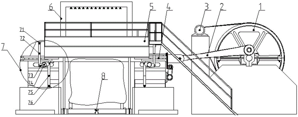
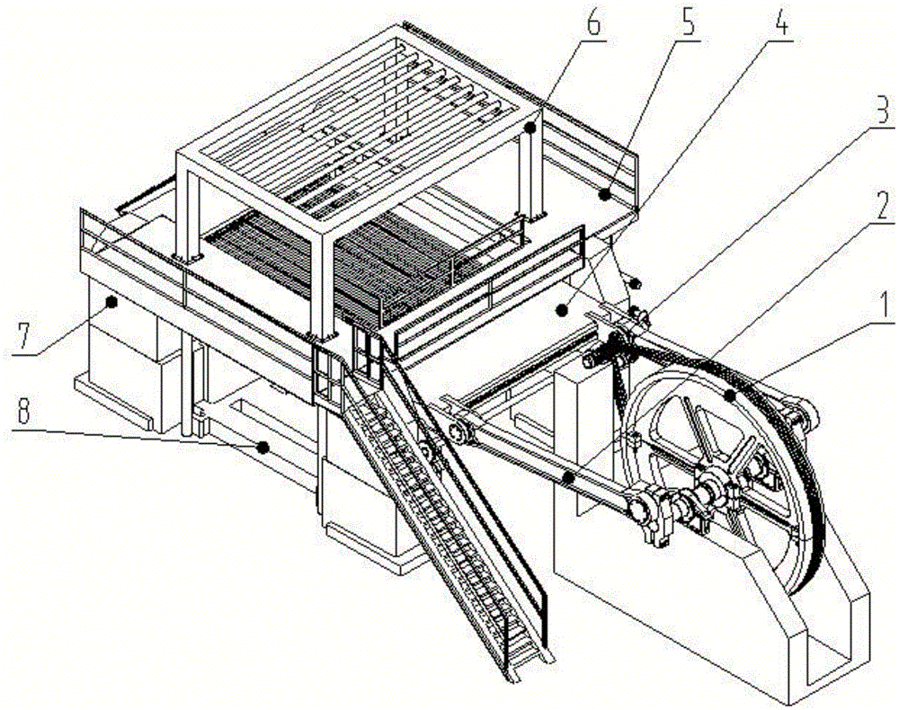
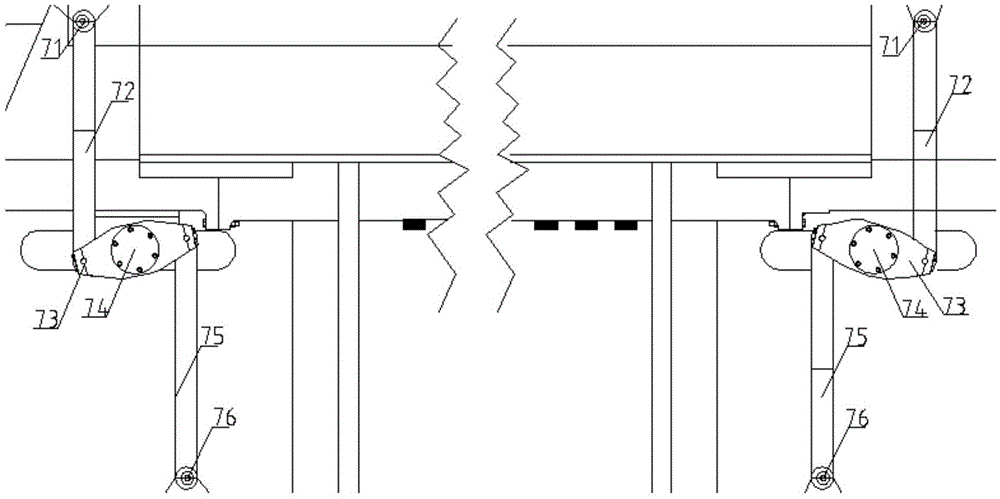
[0035] like figure 1 Shown is a single-stroke sawing device for ultra-hard stone related to the present invention, including flywheel 1, crank connecting rod 2, main motor 3, saw frame unit 4 (saw frame and diamond saw blade), frame 5, water spray Cooling device 6, hinge guide mechanism 7, block truck and stone jacking device 8. Both the saw frame unit 4 and the hinge guide mechanism 7 are arranged on the frame 5 . The hinge guide mechanism 7 includes a swing body 73 , an upper link 72 , a lower link 75 , an upper link pivot shaft 71 , a lower link pivot shaft 76 and a swing body central axis 74 . One end where the upper and lower connecting rods are connected to the frame has a certain eccentricity relative to its own original central pivot, and the other end is normally hinged with the swing body. One end of the central axis of the oscillating body is pivotally connected to the saw frame unit, and the other end is hingedly fitted with the oscillating body.

[0036] like ...

Embodiment 2

[0041] The difference from Embodiment 1 is that the upper and lower links 72, 75 of the hinge guide mechanism 7 are connected to the frame 5, and the upper link 72 is eccentric to the left, and the lower link 75 is eccentric to the right. At this time, the hinge The whole organization shows a left deflection trend. When the connecting rod swings relative to the frame, the eccentric section makes the saw frame in a cutting state during a stroke (including reversing) away from the flywheel end, and a non-cutting state during a stroke (including reversing) near the flywheel end. When the connecting rod swings to the left relative to the frame, the saw frame unit moves leftward and downward relative to the frame saw machine; when the connecting rod swings to the right, the hinge guide mechanism unit drives the saw frame unit to move rightward relative to the frame saw machine and move upwards. The eccentricity at this time makes the overall saw frame of the saw machine move in an...


PUM


Abstract

The invention discloses a processing device for one-stroke sawing of hard stones and a working method. The processing device comprises a main motor, a flywheel, a crank connecting rod, a saw frame unit, a hinge guiding device, a waste material vehicle jacking device, a rack, a water spraying cooling device and the like, wherein the saw frame unit and the guiding device are arranged on the rack. The processing device is characterized in that hinge guiding device mainly comprises a swinging body, an upper connecting rod, a lower connecting rod, an upper connecting rod pivoting shaft, a lower connecting rod pivoting shaft and a swinging body middle shaft; the ends, which are connected with the rack, of the upper connecting rod and the lower connecting rod are certainly eccentric relative to the pivoting shafts of the upper connecting rod and the lower connecting rod, and the other end of the upper connecting rod and the other end of the lower connecting rod are hinged with the swinging body; one end of the swinging body middle shaft is pivoted on the saw frame unit and the other end of the swinging body middle shaft is hinged to and matched with the swinging body. According to the processing device, the one-stroke sawing of a frame saw can be realized, so that a saw frame can be lifted in an operation process and has impact in a cutting process; a cutter clamping phenomenon is not easy to occur and the service life of a cutter head is prolonged; the abrasion of the cutter head and the stones is reduced and the energy consumption is lowered.

Description

technical field [0001] The invention relates to a processing device and working method for single-stroke sawing hard stone, belonging to the technical field of stone processing equipment. Background technique [0002] At present, in the processing of large stone slabs, the invention patent CN201020173872.8 filed by Liu Zhi of Fujian Nanan Feizhou Machinery Co., Ltd. mentioned a hinged frame saw, which can cut soft stone (such as marble) At the same time, the back and forth swing of the hinge ensures the straightness of the oscillating body during the movement, so that the diamond particles can cut the marble. However, this equipment still has the following losses: because the saw blade is cutting horizontally and reciprocatingly, the saw blade is always in the cutting state, and some diamond particles are not The ability to sharpen the blade in time causes the diamond particles to fall off easily, and it is difficult to remove the fallen diamond from both ends of the block i...

Claims


Application Information

Patent Timeline
Patent Type & Authority Patents(China)
IPC IPC(8): B28D1/02B28D7/00
CPCB28D1/02B28D7/00
Inventor 张进生张恒王志孙芹邢举学方金岩许东
Owner SHANDONG UNIV
Why Eureka
Try Eureka