Cantilever woodworking center frame with chip removal

A technology of machining center and chip removal device, applied in the direction of wood processing appliances, manufacturing tools, multi-purpose machinery, etc., can solve the problems of cluttered configuration, hidden danger of operation safety, unsightly appearance, etc., to improve the overall layout, save manufacturing materials, shorten the The effect of pipe distance

Active Publication Date: 2016-04-06
NANXING MACHINERY CO LTD
View PDF7 Cites 0 Cited by
  • Summary
  • Abstract
  • Description
  • Claims
  • Application Information

AI Technical Summary

Problems solved by technology

[0004] (1) There is no chip removal device, resulting in the accumulation of coarse wood chips that cannot be sucked away by the vacuum tube on the rack, which is difficult to clean, and large pieces of wood chips that are not discharged in time will also bring hidden dangers to operational safety; in view of this situation, Some furniture manufacturers manually clean the accumulated sawdust from time to time, which will affect the effective use time of the machine and reduce the processing efficiency of the machine;
[0005] (2) The structural design of the frame is not reasonable enough, the important stress-bearing parts are not supported by reinforcing ribs, and the rigidity is not enough. During the use of the machine, there will be vibration, which seriously affects the processing accuracy of the machine;
[0006] (3) The current vacuum gas storage tank is usually installed separately on the outside of the frame, which affects the layout of the whole machine and is not beautiful. In addition, the vacuum gas storage tank and the gas equipment need to be connected with a separate vacuum tube, and the vacuum tube is long and the configuration is messy , looks very untidy

Method used


Image

  • Cantilever woodworking center frame with chip removal
  • Cantilever woodworking center frame with chip removal
  • Cantilever woodworking center frame with chip removal

Examples


Embodiment Construction

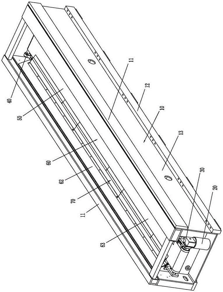
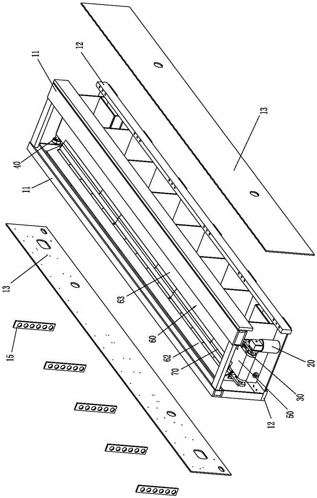
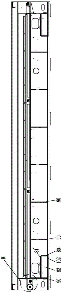
[0051] Please refer to Figure 1 to Figure 10 As shown, it shows the specific structure of the embodiment of the present invention, the frame of this kind of cantilever type wood processing center with chip removal device includes a frame body 10 and a motor 20 installed in the frame body 10, and a driving wheel 30 , Tension pulley 40, conveyor belt 50, chip flute body 60.

[0052]Wherein, a hollow cavity 101 is formed inside the frame body 10, and the hollow cavity 101 has an open upper end; in this embodiment, the frame body 10 includes two upper beams 11 and two lower beams 12 located on both sides, and A side steel plate 13 is connected between the upper and lower beams, a reinforcing rib 15 is added between the upper and lower beams on at least one side, and a bottom steel plate 14 is connected between the two lower beams 12; the upper and lower beams are made of steel plates It is welded, and the side steel plate 13, the bottom steel plate 14 and the reinforcing rib 15 ...


PUM


Abstract

The invention discloses a cantilever type rack with a chip removal device in a wood processing center. The cantilever type rack comprises a rack body, a motor, a driving wheel, a tensioning wheel, a conveyor belt, a chip removal tank body and a vacuum air storage tank, wherein the motor, the driving wheel, the tensioning wheel, the conveyor belt, the chip removal tank body and the vacuum air storage tank are mounted in the rack body; a hollow cavity is formed inside the rack body, the chip removal tank body comprises a base plate and two side plates, the upper ends of the two side plates are respectively connected onto the rack body, and the base plate and the two side plates form a chip removal groove, extending in the same direction as that of the hollow cavity, in a surrounding manner; the driving wheel and the tensioning wheel are respectively mounted at the positions of the two ends of the chip removal groove, the motor is connected to the driving wheel in a driving mode, the conveyor belt is in transmission connection between the driving wheel and the tensioning wheel, and at least the conveyor belt on the upper side penetrates through the chip removal groove; a support plate is arranged below the conveyor belt on the upper side, dust baffle plates are respectively arranged at the positions of the two sides inside the chip removal groove, the upper ends of the dust baffle plates are connected onto the corresponding side plates of the chip removal tank body, and the lower ends of the dust baffle plates are in contact with the conveyor belt on the upper side. Accumulated wood chips can be automatically treated at any time, so that the cantilever type rack is convenient, quick, time-saving and labor-saving, and facilitates increasing of the utilization rate and improvement of the processing efficiency of the machine.

Description

technical field [0001] The invention relates to the technology in the field of wood processing centers, in particular to a frame with a chip removal device of a cantilever type wood processing center. Background technique [0002] my country's furniture is mainly made of wooden furniture, especially panel furniture, which accounts for the vast majority. The panel profiles are processed by traditional woodworking machinery, and the processing procedures are numerous; and through the development of wood processing centers, one-time clamping, and then through automatic processing during processing. A complete product can be processed by changing the tool to complete multiple processes or all processes. Compared with traditional woodworking machinery processing, it has made great progress. [0003] However, the frame of the existing cantilever type wood processing center still has many deficiencies, such as: [0004] (1) There is no chip removal device, resulting in the accumula...

Claims


Application Information

Patent Timeline
Patent Type & Authority Patents(China)
IPC IPC(8): B27C9/00
CPCB27C9/00
Inventor 邓金贵邱宇董慧涛赵莉莉黄剑锋王勇
Owner NANXING MACHINERY CO LTD
Why Eureka
Try Eureka