Leakage current detection method and device
A leakage current detection and leakage current technology, which is used in measurement devices, electronic circuit testing, marginal circuit testing, etc., can solve problems such as limited detection ratio, failure, and difficulty in stable leakage current testing, and achieve high detection accuracy and detection efficiency. The effect of high and large detection ratio
- Summary
- Abstract
- Description
- Claims
- Application Information
AI Technical Summary
Problems solved by technology
Method used
Image
Examples
Embodiment 1
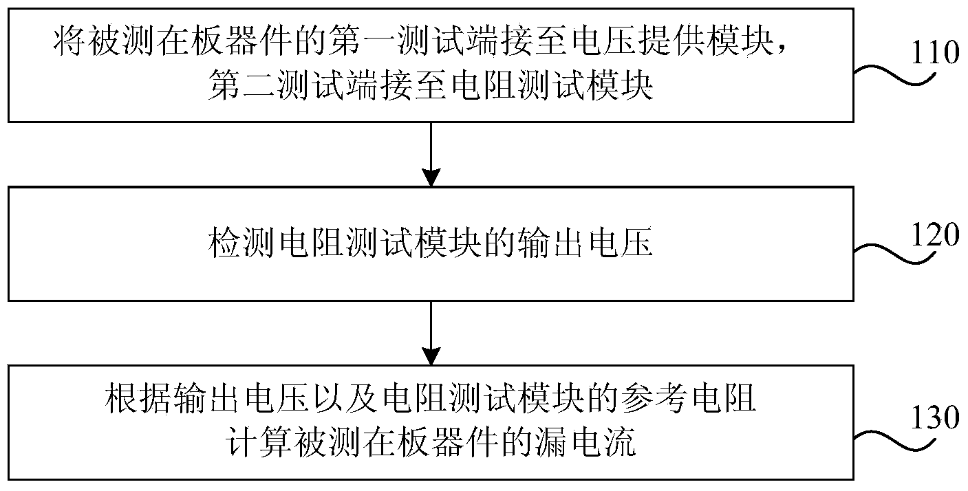
[0056] figure 2 Is a flowchart of a leakage current detection method provided by an embodiment of the present invention, such as figure 2 As shown, the method is applied to the leakage current detection of on-board devices on a printed circuit board assembly (PCBA) board. The method includes:
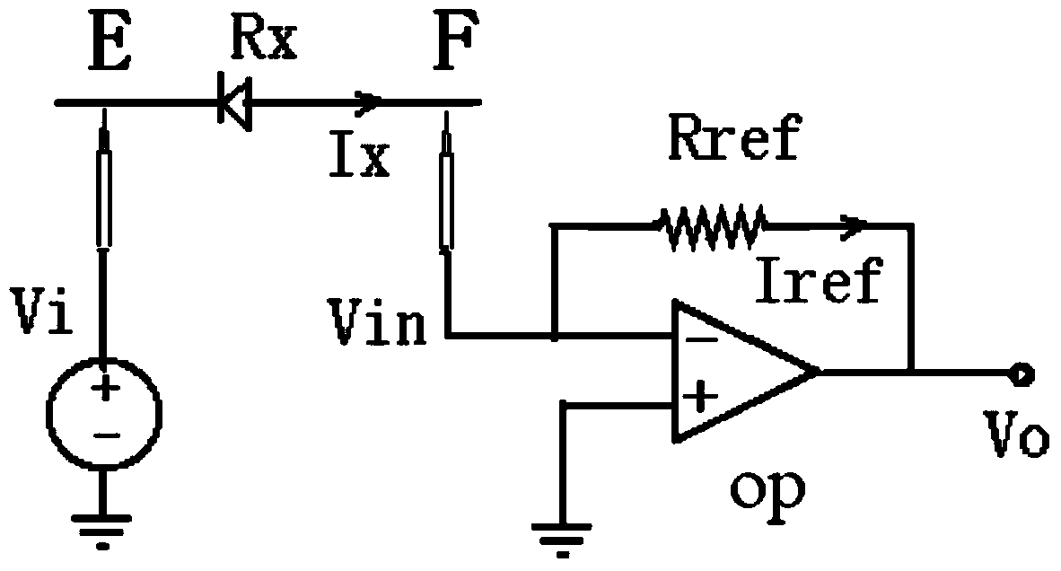
[0057] Step S110: Connect the leakage input terminal of the device under test to the voltage supply module, and connect the leakage output terminal to the resistance test module.
[0058] Specifically, the tested on-board device is an on-board isolated device, that is, an on-board device that is not connected to any other devices. For the isolated device on the board, in the single-board PCB design stage, a test point is respectively arranged at the leakage input end and the leakage output end of the isolated device on the board in advance. For devices with multiple pins, two pins can be selected as the leakage input terminal and the leakage output terminal according to actual needs. For...
Embodiment 2
[0082] Figure 4 Is a flowchart of a leakage current detection method provided by another embodiment of the present invention, such as Figure 4 As shown, Figure 4 The illustrated embodiment is the same as figure 2 The main difference of the illustrated embodiment is Figure 4 The illustrated embodiment is used to detect the leakage current of an on-board device connected to other devices, and the method mainly includes:
[0083] Step 210: Isolate the device under test from other connected devices.
[0084] The purpose of isolation is to eliminate the bypass influence of other connected devices on the device under test, and to ensure that the current flowing through the second resistor R2 is 0, that is, to ensure I 2 =0 (such as Figure 5 Shown), and makes I X =I ref .
[0085] In this embodiment, isolation is performed in the following manner.
[0086] Such as Figure 5 As shown, other devices connected to the leakage input end of the device under test Rx are equivalent to the firs...
Embodiment 3
[0097] Image 6 It is a schematic structural diagram of a leakage current detection device provided by an embodiment of the present invention, such as Image 6 As shown, the device 100 includes a voltage providing module 11, a resistance testing module 12, and a control module 13.
[0098] Among them, the voltage supply module 11 is connected to the leakage input end of the device under test 14 to provide a fixed voltage relative to the reference ground for the device under test 14; the resistance test module 12 is connected to the leakage current of the device under test 14 The output terminal is used to provide a reference resistance; the control module 13 is connected to the resistance test module 12 and the voltage supply module 11, and is used to calculate the leakage current flowing through the measured on-board device 14 according to the output voltage of the resistance test module 12 and the reference resistance.
[0099] The on-board device 14 to be tested in this embodimen...
PUM
 Abstract
Description
Claims
Application Information
 - R&D
- Intellectual Property
- Life Sciences
- Materials
- Tech Scout
- Unparalleled Data Quality
- Higher Quality Content
- 60% Fewer Hallucinations
Browse by: Latest US Patents, China's latest patents, Technical Efficacy Thesaurus, Application Domain, Technology Topic, Popular Technical Reports.
© 2025 PatSnap. All rights reserved.Legal|Privacy policy|Modern Slavery Act Transparency Statement|Sitemap|About US| Contact US: help@patsnap.com


