Heat supply conveying pipeline of heating tank in chemical plant

A technology for transportation pipelines and chemical plants, applied in the field of heating transportation pipelines, can solve problems such as noise pollution, loud noise, and impact on the environment, and achieve the effects of avoiding noise pollution, reducing noise, and slowing down the speed

Inactive Publication Date: 2015-02-11
CHONGQING THRIVE CHEM
View PDF0 Cites 3 Cited by
  • Summary
  • Abstract
  • Description
  • Claims
  • Application Information

AI Technical Summary

Problems solved by technology

In the process of central heating, use the hot water pump installed at the heating tank to transport the hot water after heat exchange to each room through the heating pipe, so that each room can get a suitable indoor temperature; because the hot water pump and the heating pipe are rigidly connected At present, the heating pipe generally adopts a single-layer structure, and the inner wall of the pipe is a smooth arc structure. The disadvantage of the heating pipe with this structure is: when hot water flows in the heating pipe, due to the The inner wall is a smooth structure, and the water flow directly impacts on the inner wall of the heating pipe, which makes a lot of noise during the heating process, which brings a lot of inconvenience to office and life, thus causing noise pollution and affecting the surrounding environment

Method used


Image

  • Heat supply conveying pipeline of heating tank in chemical plant

Examples


Embodiment Construction

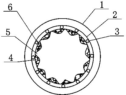
[0013] Below in conjunction with accompanying drawing and embodiment the technical solution of the present invention is further described:

[0014] Such as figure 1 As shown, the present invention provides a heat supply pipeline for a heating tank in a chemical plant, comprising a silencing pipe 2 arranged in the pipe wall of the heating pipe 1, a silencing hole 3 is arranged in the side wall of the silencing pipe 2, and a silencing hole 3 is arranged in the wall of the silencing pipe 1. A plurality of protrusions 6 with a triangular cross-section are arranged on the inner wall of the pipe through hole of 2. The protrusions 6 are hollow structures filled with sound-proof cotton 4, and an arc surface that can buffer water flow is formed between each two protrusions 6. The buffer tank 5, the diameter of the silencer hole 3 is set to 4cm, the section height of the protrusion 6 is set to 6cm, the material of the protrusion 6 is rubber, and a shut-off valve (not shown in the figur...


PUM


Abstract

The invention relates to the technical field of chemical equipment, and in particular relates to a heat supply conveying pipeline of a heating tank in a chemical plant. The heat supply conveying pipeline comprises a heat supply pipe which is connected with the heating tank, wherein a hush pipe is arranged inside the wall of the heat supply pipe; hush holes are formed inside the side wall of the hush pipe; a complex number of bulges of which the cross sections are triangular are arranged on the inner wall of the pipe through hole of the hush pipe; the bulges adopt hollow structures filled with sound-proof cotton; a buffer groove which can buffer water flow and takes the shape of a circular arc camber is formed between every two bulges. By adopting the technical scheme, the heat supply conveying pipeline of the heating tank in the chemical plant can alleviate the impact and reduce the noise.

Description

technical field [0001] The invention relates to the technical field of chemical equipment, in particular to a heat supply pipeline for a heating tank in a chemical plant. Background technique [0002] At present, many chemical industries in my country use the steam waste heat after production and use to exchange heat with heat exchangers to achieve uninterrupted central heating. In the process of central heating, use the hot water pump installed at the heating tank to transport the hot water after heat exchange to each room through the heating pipe, so that each room can get a suitable indoor temperature; because the hot water pump and the heating pipe are rigidly connected At present, the heating pipe generally adopts a single-layer structure, and the inner wall of the pipe is a smooth arc structure. The disadvantage of the heating pipe with this structure is: when hot water flows in the heating pipe, due to the The inner wall is a smooth structure, and the water flow dire...

Claims


Application Information

Patent Timeline
Patent Type & Authority Applications(China)
IPC IPC(8): F16L9/21F24D3/10
CPCF16L9/21F24D3/1058
Inventor 赵华文
Owner CHONGQING THRIVE CHEM
Why Eureka
Try Eureka