
Fuel injection device

A fuel injection device and fuel injection valve technology, applied in turbine/propulsion fuel delivery systems, combustion chambers, combustion methods, etc., can solve the problems of pilot injection valve combustion efficiency or poor ignition/flame stability, etc.

Active Publication Date: 2015-02-04
KAWASAKI JUKOGYO KK
View PDF9 Cites 12 Cited by
  • Summary
  • Abstract
  • Description
  • Claims
  • Application Information

AI Technical Summary

Problems solved by technology

[0006] In the concentric fuel injection valve, at low output where only the pilot injection valve operates, a large amount of air also flows in the flow path of the main injection valve, so this air interferes with the pilot combustion, and there is combustion efficiency or ignitability / flame of the pilot injection valve Risk of poor stability

Method used


Image

  • Fuel injection device
  • Fuel injection device
  • Fuel injection device

Examples


Embodiment Construction

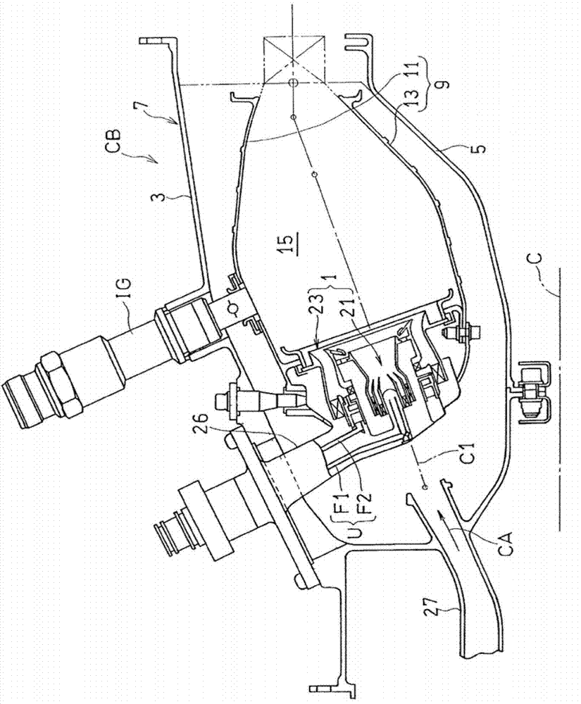
[0025] Hereinafter, preferred embodiments of the present invention will be described with reference to the drawings. figure 1 A combustor CB of a gas turbine engine including a fuel injection device 1 according to an embodiment of the present invention is shown. The combustor CB mixes and combusts fuel in compressed air CA supplied from a not-shown compressor of the gas turbine engine, and sends high-temperature / high-pressure combustion gas generated by the combustion to a turbine to drive the turbine.

[0026] The combustor CB has an annular shape, and an annular outer cover 3 arranged concentrically with the engine rotation axis C and an annular inner cover 5 inside it constitute a combustor case 7 having an annular inner space. In the annular inner space of the burner housing 7 , an annular combustion cylinder 9 is arranged concentrically with the burner housing 7 . The combustion tube 9 is composed of an annular outer liner 11 and an annular inner liner 13 arranged concen...


PUM


Abstract

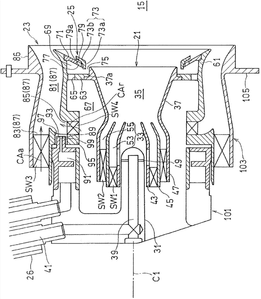
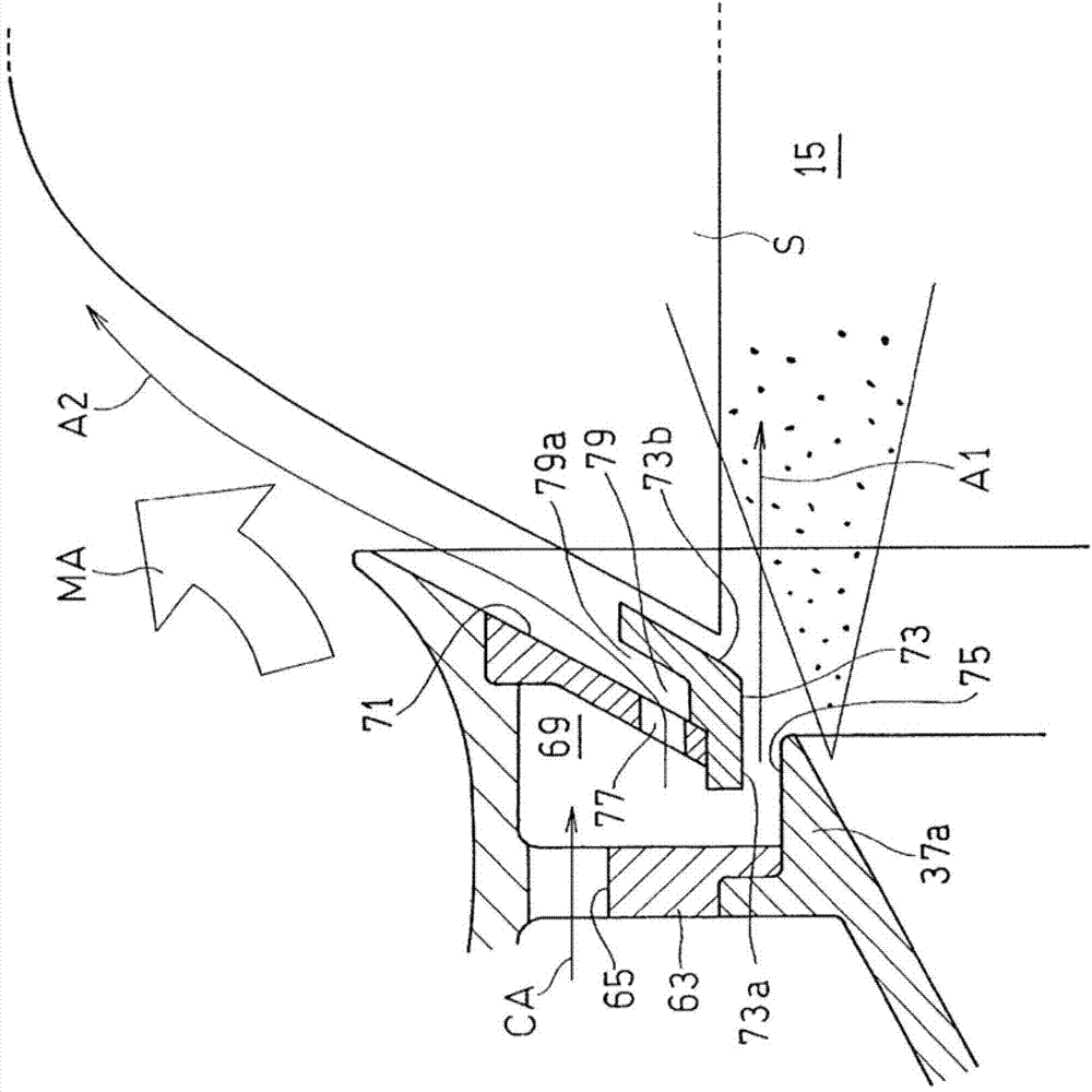
A fuel injection device for supplying fuel to compressed air from a compressor and combusting the fuel, wherein a pilot fuel injection valve (21), a main fuel injection valve (23) disposed on the outer periphery of the pilot fuel injection valve, and an air injection unit (25) disposed between the end part of the outlet of the pilot fuel injection valve and the main fuel injection valve are provided; the air injection unit is provided with a bulkhead plate (71) for partitioning the air injection unit from a combustion chamber, a baffle plate (73) provided on the downstream side of the bulkhead plate, a first opening (75) opened to the downstream side between the baffle plate and the end part of the outlet of the pilot fuel injection valve, and a second opening (77) provided to the bulkhead plate and used for supplying compressed air between the baffle plate and the bulkhead plate; and the baffle plate is provided with an inclined part (73b) that is inclined in the downstream direction diagonally outward in the radial direction in relation to the axial center.

Description

[0001] related application [0002] This application claims the priority of Japanese Patent Application No. 2012-129681 for which it applied on June 7, 2012, The content is taken in as a part as a part by reference here. technical field [0003] The present invention relates to a fuel injection device which is used in, for example, a gas turbine engine or the like, and which includes a composite fuel injection valve in which a plurality of fuel nozzles are combined. Background technique [0004] In recent years, in consideration of the environment, reduction of harmful substances such as NOx (nitrogen oxides) emitted from gas turbines has been demanded. The fuel nozzles of conventional gas turbine combustors for aircraft use a diffusion combustion method. In this method, since the combustion reaction proceeds at a stoichiometric ratio, the flame temperature becomes high. Since the emission of NOx increases exponentially with respect to the flame temperature, lowering the fl...

Claims


Application Information

Patent Timeline
Patent Type & Authority Applications(China)
IPC IPC(8): F23R3/18F02C7/22F23R3/14F23R3/28F23R3/34
CPCF23R3/14Y02T50/675F23R3/28F23R3/34Y02T50/60F23R3/16F23R3/18F23R3/343
Inventor 松山龙佐小林正佳堀川敦史藤原仁志
Owner KAWASAKI JUKOGYO KK
Learn More