
Combustion chamber adopting swirl vane tail edge pre-film atomization mode

A technology of swirling blades and combustion chambers, applied in the direction of combustion chambers, continuous combustion chambers, combustion methods, etc., can solve the problems of shortening the length of the flame and the length of the flame tube, long mixing distance of oil and gas, and coking of fuel oil, etc., to improve the temperature distribution The effect of improving quality, widening the stable working range and improving the service life

Active Publication Date: 2015-02-04
INST OF ENGINEERING THERMOPHYSICS - CHINESE ACAD OF SCI
View PDF15 Cites 13 Cited by
  • Summary
  • Abstract
  • Description
  • Claims
  • Application Information

AI Technical Summary

Problems solved by technology

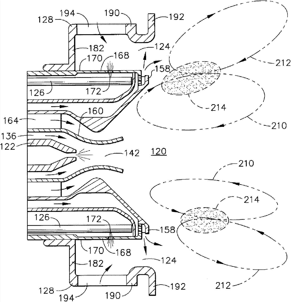
[0005] However, for the above-mentioned multiple combustion chambers, the fuel is injected laterally into the swirling air of the main combustion stage, and the fragmentation and atomization of the fuel mainly depends on the aerodynamic force of the swirling air. Longer, it is necessary to accurately control the relevant parameters to achieve the ideal mixing effect, which is not conducive to shortening the length of the flame and the length of the flame tube
In addition, in the case of low fuel flow, due to the small initial momentum of the fuel, the fuel will flow along the wall under the action of the swirling air, resulting in fuel coking and other consequences

Method used


Image

  • Combustion chamber adopting swirl vane tail edge pre-film atomization mode
  • Combustion chamber adopting swirl vane tail edge pre-film atomization mode
  • Combustion chamber adopting swirl vane tail edge pre-film atomization mode

Examples


Embodiment Construction

[0033] In order to make the object, technical solution and advantages of the present invention clearer, the present invention will be described in further detail below in conjunction with specific embodiments and with reference to the accompanying drawings. It should be noted that, in the drawings or descriptions of the specification, similar or identical parts all use the same figure numbers. Implementations not shown or described in the accompanying drawings are forms known to those of ordinary skill in the art. Additionally, while illustrations of parameters including particular values ​​may be provided herein, it should be understood that the parameters need not be exactly equal to the corresponding values, but rather may approximate the corresponding values ​​within acceptable error margins or design constraints. The directional terms mentioned in the embodiments, such as "upper", "lower", "front", "rear", "left", "right", etc., are only referring to the directions of the...


PUM

PropertyMeasurementUnit
Thicknessaaaaaaaaaa

Abstract

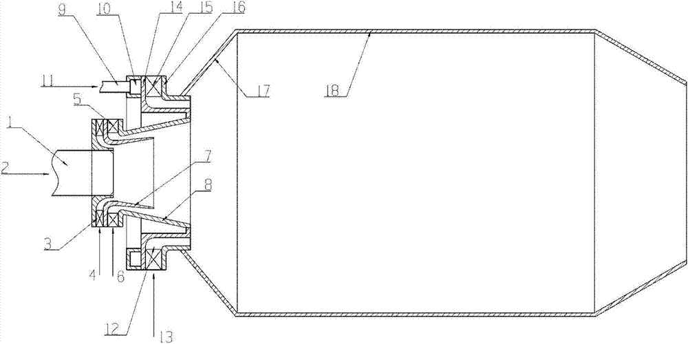
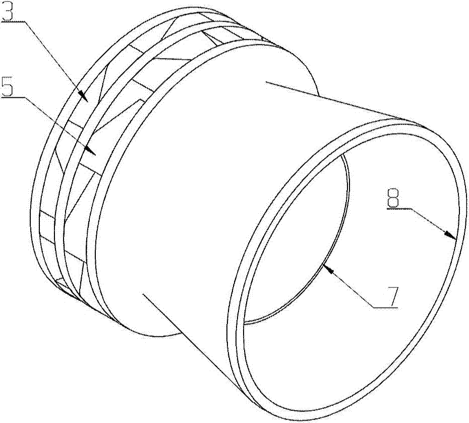
The invention provides a combustion chamber adopting a swirl vane tail edge pre-film atomization mode. The combustion chamber comprises a combustion chamber flame tube, a center level oil and gas mixing assembly and a main combustion level oil and gas mixing assembly which is arranged at the front end of the combustion chamber flame tube and the periphery of the center level oil and gas mixing assembly. The main combustion level oil and gas mixing assembly comprises a main combustion level swirl channel, N wedge-shaped swirl vanes and M vane interior oil paths; the N wedge-shaped swirl vanes are slantly fixed to the interior of the main combustion level swirl channel, and the M vane interior oil paths are arranged in at least one part of wedge-shaped swirl vanes respectively; the front end of each vane interior oil path is connected with a main combustion level oil cavity, and the tail end of the each vane interior oil path extends to the tail edge of the corresponding wedge-shaped swirl vane; the M is smaller than or equal to the N. The swirl vanes are wedge-shaped; velocity gradients are formed at the tail edges of the swirl vanes; a fuel liquid film flowing out of the tail edges of the swirl vanes is rapidly shorn and atomized under the action of the velocity gradients; the oil and gas blending distance is short, and the flame length and the length of the flame tube are shortened.

Description

technical field [0001] The invention relates to the technical field of engine combustion chambers, in particular to a combustion chamber adopting a method of mixing oil and gas with pre-film atomization at the trailing edge of swirl blades. Background technique [0002] In order to further reduce the impact of civil aviation engines on the upper atmosphere, the requirements of the International Civil Aviation Organization on the pollutant emissions (especially NOx) of civil aviation engines are becoming more and more stringent. Studies have found that nitrogen oxides tend to form in large quantities in the high-temperature area of ​​the combustion chamber, so the main measure to reduce pollutant emissions in the combustion chamber is to avoid local high temperatures in the combustion area. Today's mainstream low-pollution combustor technologies include Lean Premixed-Prevaporized combustor (LPP), Lean Direct Injection (LDI) and rich-quench-lean (Rich burn -Quick quench-Lean ...

Claims


Application Information

Patent Timeline
IPC IPC(8): F23R3/58F23R3/38F23R3/36
Inventor 杨金虎刘存喜张楷雨刘富强徐纲朱俊强
Owner INST OF ENGINEERING THERMOPHYSICS - CHINESE ACAD OF SCI
Learn More