
Numerical-control cutter measuring device of spiral bevel gear milling machine

A technology of spiral bevel gear and gear milling machine, which is applied in the direction of measuring/indicating equipment, metal processing machinery parts, metal processing equipment, etc. It can solve the problems of affecting the cutting precision, damaging the meter head, and assembly error of the tool spindle, so as to avoid damage Meter, accurate measurement effect

Inactive Publication Date: 2015-02-04
TIANJIN NO 1 MACHINE TOOL WORKS
View PDF6 Cites 0 Cited by
  • Summary
  • Abstract
  • Description
  • Claims
  • Application Information

AI Technical Summary

Problems solved by technology

The outer cutter and inner cutter of the milling cutter are ground and then installed on the cutter body. There will be certain errors due to adjustment and detection; There may be radial runout errors of the outer cutter and inner cutter, which will affect the gear cutting accuracy
Therefore, in the process of processing and producing contour bevel gears, it is necessary to regularly measure the radial runout error of the outer cutter, the top of the inner cutter and the side cutting edge. When the traditional dial indicator is used to measure the outer cutter or inner cutter, the inner cutter ( In order to effectively get out of the way of adjacent inner knives (outer knives) to avoid damage to the meter head, and to accurately measure the radial runout error of the inner and outer blades of the cutter head, it is necessary to A Tool Measuring Device Suitable for Equal Height Tooth Milling

Method used


Image

  • Numerical-control cutter measuring device of spiral bevel gear milling machine
  • Numerical-control cutter measuring device of spiral bevel gear milling machine

Examples


Embodiment Construction

[0014] In order to further understand the invention content, characteristics and effects of the present invention, the following examples are given, and detailed descriptions are as follows in conjunction with the accompanying drawings:

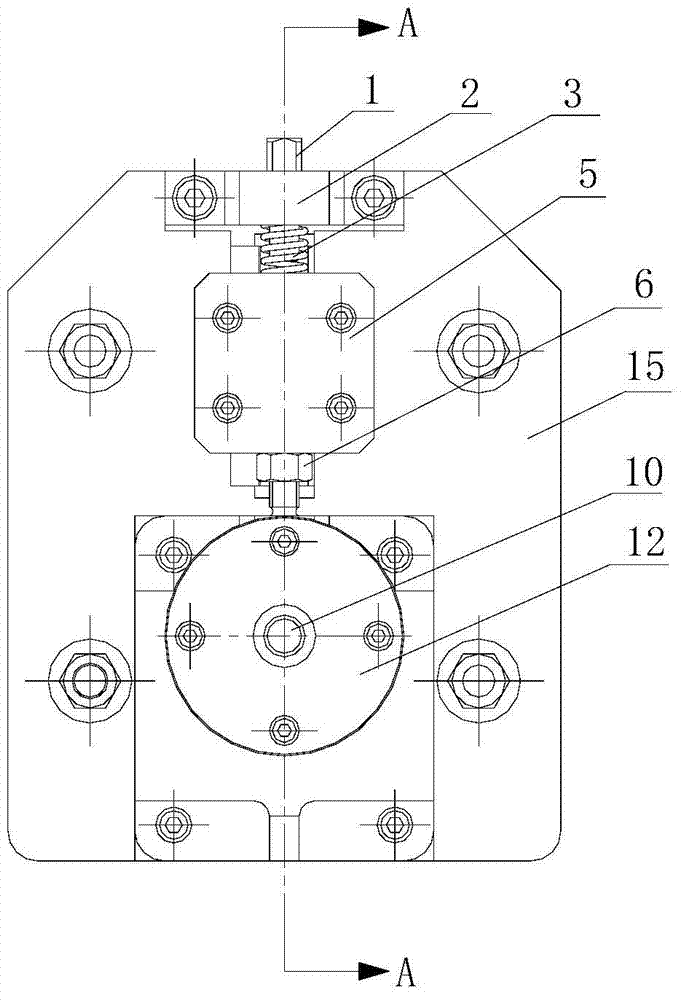
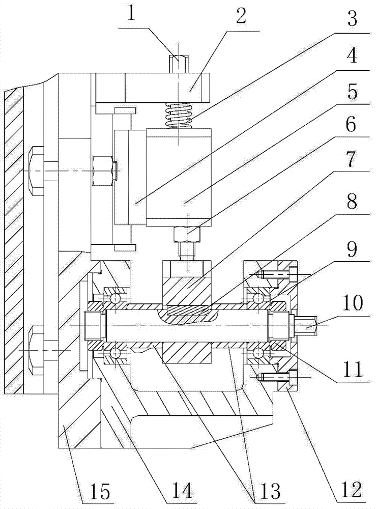
[0015] see figure 1 and figure 2 , the CNC spiral bevel gear milling machine tool measuring device, including a base plate 15 installed on the end cover of the cradle, a tailstock 2 and a guide rail 16 located below the tailstock are installed on the upper side of the base plate, and the guide rail is equipped with a Its guide rail slide block 4 that slides up and down, a bearing seat 14 is fixedly installed on the bottom side of the bottom plate, a rotating shaft 10 is housed in the described bearing seat, and a cam 7 is connected with a key 8 on the rotating shaft, and the cam and the top Rod 6 is connected, and described ejector rod is connected with table base 5 that is installed on the guide rail slider, and described table base withst...


PUM


Abstract

The invention relates to a numerical-control cutter measuring device of a spiral bevel gear milling machine. The numerical-control cutter measuring device is characterized by comprising a bottom plate arranged on an end cover of a rocking platform, wherein one side of the upper part of the bottom plate is provided with a tail frame and a guiding rail positioned under the tail frame; the guiding rail is provided with a guiding-rail sliding block which can slide up and down along the guiding rail; a bearing seat is fixedly arranged at one side of the lower part of the bottom plate; a rotary shaft is arranged in the bearing seat; a cam is connected on the rotary shaft by keys and is connected with a pushing rod which is connected with a gauge stand arranged on the guiding-rail sliding block; the gauge stand supports a spring fixed on the tail frame. The numerical-control cutter measuring device has the advantages that when the radial run-out error of edges of outer cutters (inner cutters) of a cutter disc is measured, not only the adjacent inner cutters (outer cutters) can be effectively avoided so as to prevent from damaging a gauge head, but also the cutter measuring device can return the starting position accurately when the edges of the adjacent outer cutters (inner cutters) are measured, so that the measurement is more accurate.

Description

technical field [0001] The invention belongs to the field of gear processing machine tools, in particular to a tool measuring device for a numerically controlled spiral bevel gear milling machine. Background technique [0002] At present, the design of the spiral bevel gear of the automobile drive axle mainly adopts two tooth systems: tapered teeth and contour teeth. Tapered gear is a traditional main processing method, which has been widely used at home and abroad for a long time. In recent years, the design calculation and processing adjustment of contour teeth have been greatly simplified, and the adjustment of the contact area is also simpler and faster, and contour gears have been more and more widely used in the automotive industry. The traditional milling cutters used for machining equal-height teeth and tapered teeth are different. According to the different rotation directions of the gears to be processed, the arrangement order of various cutter teeth is different....

Claims


Application Information

Patent Timeline
Patent Type & Authority Applications(China)
IPC IPC(8): B23Q17/09
CPCB23Q17/2233
Inventor 赵辰婧宋国栋王威吴杰杨威
Owner TIANJIN NO 1 MACHINE TOOL WORKS
Learn More