
Direct drive LED lighting system controlled by integrated control circuit

An integrated control circuit and LED lighting technology, applied in the field of LED lighting, can solve the problems of low drive power supply efficiency of LED lamps, high drive current of high-power lighting systems, high cost of wires and cables, and achieve good anti-light flicker characteristics and low cost , the effect of prolonging life

Inactive Publication Date: 2015-01-28
HANGZHOU HPWINNER OPTO CORP
View PDF4 Cites 4 Cited by
  • Summary
  • Abstract
  • Description
  • Claims
  • Application Information

AI Technical Summary

Problems solved by technology

[0003] As an advanced light-emitting device, LED is widely used in road lighting, but the existing LED street lighting system drives are powered by single-phase AC mains, such as single-phase AC mains, the LED road lighting driven by this single-phase AC mains The technology has two obvious disadvantages, one is that the driving current of the road high-power lighting system is large, and the cost of the required wires and cables is high; the other is that the driving power efficiency of LED lamps is relatively low, generally only about 90%

Method used


Image

  • Direct drive LED lighting system controlled by integrated control circuit
  • Direct drive LED lighting system controlled by integrated control circuit
  • Direct drive LED lighting system controlled by integrated control circuit

Examples


Embodiment 1

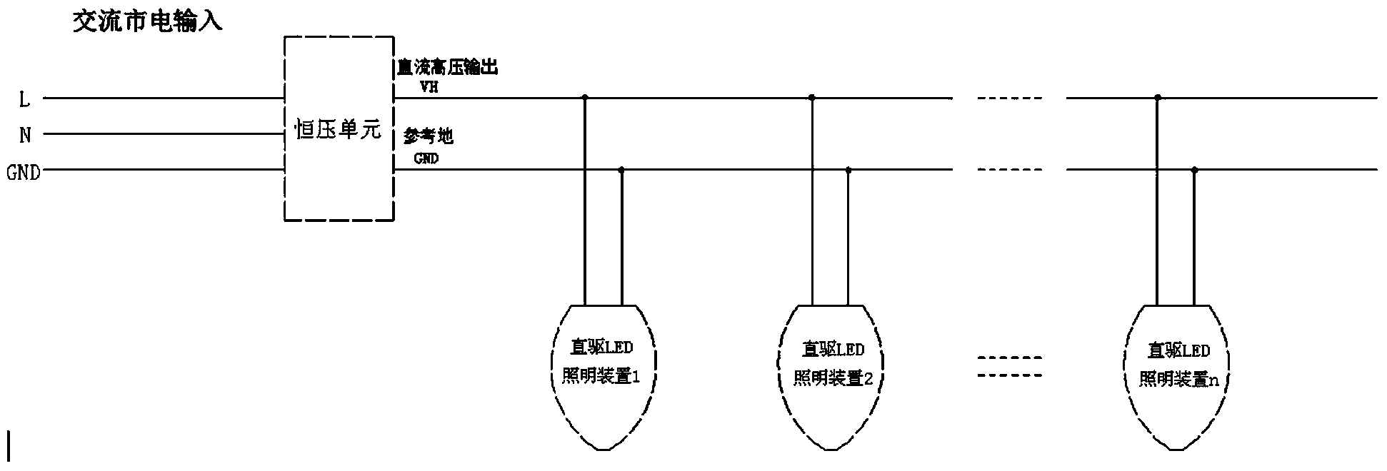
[0056] Please refer to figure 1 , figure 2 and Figure 4 , this embodiment has additional specific improvements on the basis of the above description of the basic solution.

[0057] In this embodiment, the direct-drive LED lighting device includes a substrate on which several LED circuits are arranged, and several LED circuits are connected in parallel between the high-voltage output terminal VH and the reference ground terminal GND. The full-page LED lighting device using a single substrate is beneficial to ensure the integrity and integrity of the lighting device.

Embodiment 2

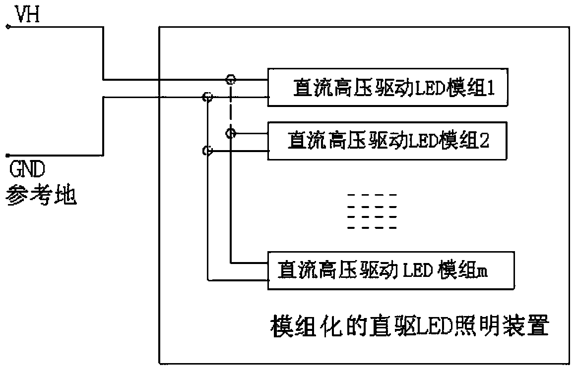
[0059] Please refer to figure 1 , image 3 and Figure 4 , this embodiment has additional specific improvements on the basis of the above description of the basic solution.

[0060] The direct-drive LED lighting device includes at least two DC high-voltage drive LED modules, each of the DC high-voltage drive LED modules includes one LED circuit, and each DC high-voltage drive LED module is correspondingly arranged in an independent on the substrate.

[0061] Several of the DC high voltage driving LED modules are connected in parallel between the high voltage output terminal VH and the reference ground terminal GND.

[0062] In this embodiment, the lighting device is configured as a module, and the lighting mode of the LED lighting system can be enriched by changing the combination of the modules. At the same time, the modularized lamp has certain advantages in heat dissipation performance, power, and assembly.

[0063] In summary, the present invention has the following be...


PUM


Abstract

The invention provides a direct drive LED lighting system controlled by an integrated control circuit. The direct drive LED lighting system controlled by the integrated control circuit comprises a constant-voltage unit and direct drive LED lighting devices. At least two direct drive LED lighting devices are connected between the direct current high-voltage output end VH and the reference ground end GND in parallel. Each direct drive LED lighting device comprises multiple LED circuits. Each LED circuit comprises at least two controlled LED particle circuit units and a normally-on LED particle circuit unit connected with the controlled LED particle circuit units in series. Each LED circuit is provided with at least two direct drive LED integrated control circuits. Each direct drive LED integrated control circuit is connected with at least one controlled LED particle circuit unit in the corresponding LED circuit unit. The direct drive LED integrated control circuits at least have the following functions of making a response to input information and controlling LED particles in the controlled LED particle circuit units to be switched on and short-circuited.

Description

technical field [0001] The invention relates to the field of LED lighting, in particular to a direct-drive LED lighting system controlled by an integrated control circuit. Background technique [0002] Light-emitting diodes are referred to as LEDs for short. Diodes made of compounds containing gallium (Ga), arsenic (As), phosphorus (P), nitrogen (N), etc. can radiate visible light when electrons and holes recombine, so they can be used to make light-emitting diodes. It is used as an indicator light in circuits and instruments, or as a text or number display. Gallium arsenide diodes emit red light, gallium phosphide diodes emit green light, silicon carbide diodes emit yellow light, and gallium nitride diodes emit blue light. Due to chemical properties, it is divided into organic light-emitting diode OLED and inorganic light-emitting diode LED. [0003] As an advanced light-emitting device, LED is widely used in road lighting, but the existing LED street lighting system dri...

Claims


Application Information

Patent Timeline
Patent Type & Authority Applications(China)
IPC IPC(8): H05B37/02
Inventor 陈凯黄建明
Owner HANGZHOU HPWINNER OPTO CORP
Learn More