
Circuit, optical module and method for protecting APD receiver

A receiver and circuit technology, applied in the field of optical transceiver modules, can solve problems such as damage to APD receivers, and achieve the effects of reducing photocurrent, reducing the risk of failure, and reducing the multiplication factor

Active Publication Date: 2015-01-28
SOURCE PHOTONICS CHENGDU
View PDF2 Cites 24 Cited by
  • Summary
  • Abstract
  • Description
  • Claims
  • Application Information

AI Technical Summary

Problems solved by technology

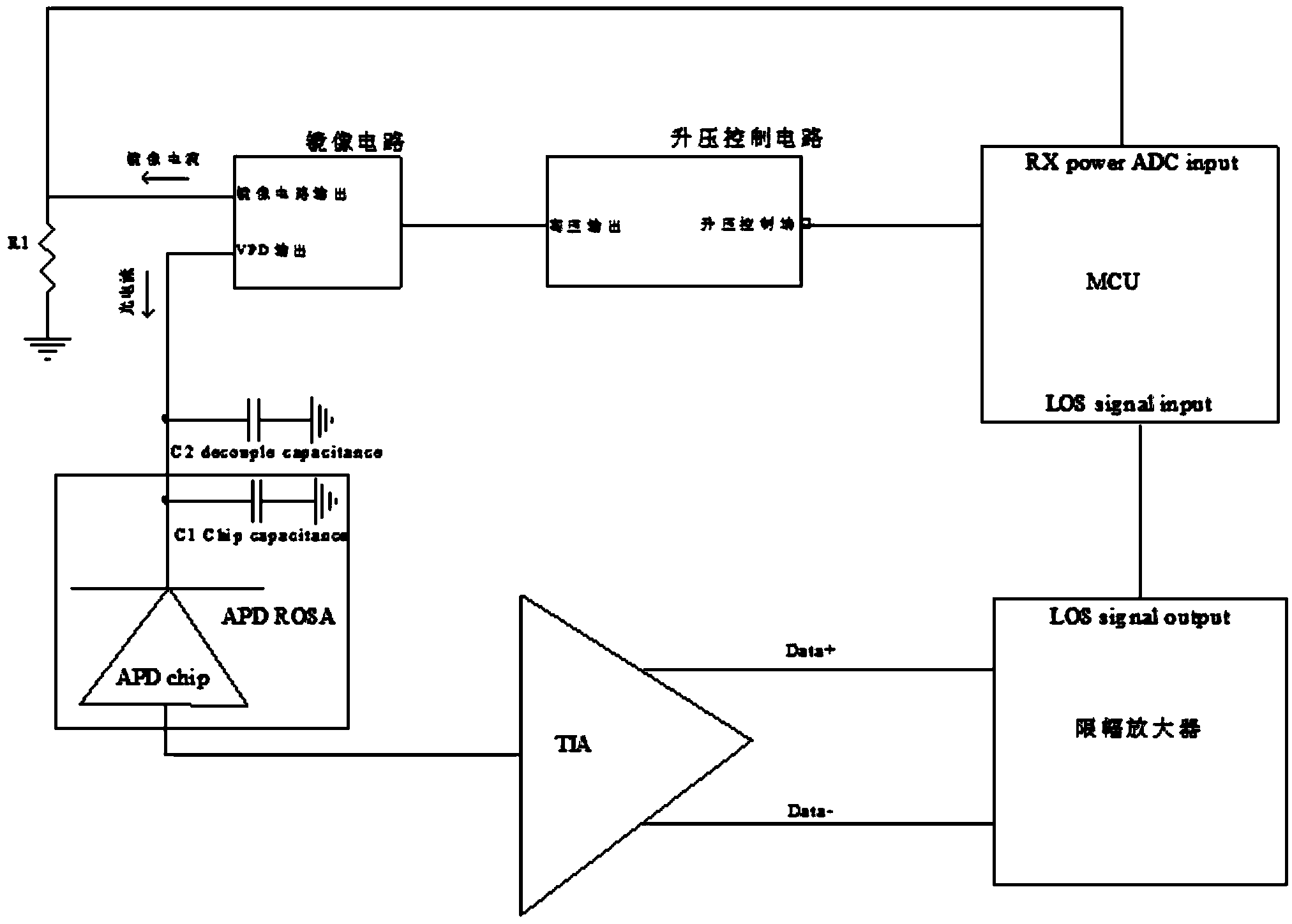
[0003] In order to obtain the best sensitivity, the MCU will control the boost control circuit to control the bias voltage of the APD receiver near the avalanche point. At this time, the multiplication factor of the APD receiver is large, and a small light input can get a larger light output. Current, when the optical power input to the APD receiver is very large, the excessive photocurrent flowing through the APD receiver will cause damage to the APD receiver

Method used


Image

  • Circuit, optical module and method for protecting APD receiver
  • Circuit, optical module and method for protecting APD receiver

Examples


Embodiment Construction

[0023] The present invention will be further described in detail below in conjunction with specific embodiments. However, it should not be construed that the scope of the above-mentioned subject matter of the present invention is limited to the following embodiments, and all technologies realized based on the content of the present invention belong to the scope of the present invention.

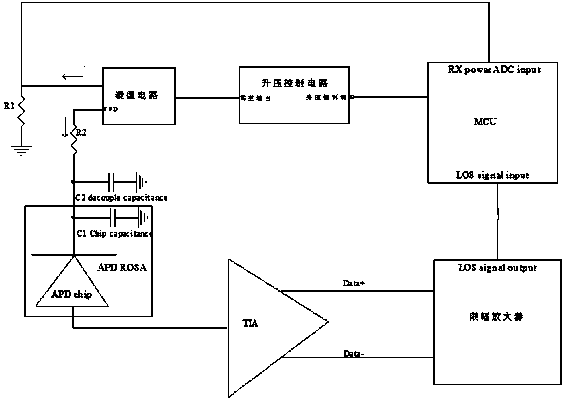
[0024] like figure 2 The shown circuit for protecting an APD receiver includes an APD receiver, the bias input of the APD receiver is grounded through the first decoupling capacitor C1 and the second decoupling capacitor C2 respectively, and the APD receiver is The bias input terminal is connected to the first output terminal VPD of the mirror circuit, the input terminal of the mirror circuit circuit is connected to the output terminal of the boosting control circuit, and the input terminal of the boosting control circuit is connected to the microprocessor MCU; the second output terminal of ...


PUM


Abstract

The invention discloses a circuit for protecting an APD receiver. The circuit comprises the APD receiver, wherein the bias input end of the APD receiver is grounded through a first decoupling capacitor and a second decoupling capacitor, the bias input end of the APD receiver is connected with a first output end of a mirror image circuit, the input end of the mirror image circuit is connected with the output end of a boost control circuit, and the input end of the boost control circuit is connected with a microprocessor; the second output end of the mirror image circuit is grounded through a first resistor and meanwhile connected to the microprocessor; the microprocessor is connected with a signal losing LOS end of a limiting amplifier which is connected with a trans-impedance amplifier (TIA), the TIA is connected with the output end of the APD receiver, a second resistor is connected between the bias input end of the APD receiver and the first output end of the mirror image circuit, and the resistance value of the second resistor ranges from 10 K ohm to 100 K ohm. Through the circuit, an APD can be effectively protected against damage, the risk that a module loses efficacy is reduced, and the service life of the optical module is prolonged.

Description

technical field [0001] The invention relates to the field of optical transceiver modules, in particular to a circuit, an optical module and a method for protecting an APD receiver in the optical module. Background technique [0002] The receiving end circuit of the optical module currently using the APD receiver is as attached figure 1 As shown, the microprocessor MCU controls the boost control circuit to output a high-voltage signal. The high-voltage signal is divided into two bias paths with proportional current output through the mirror current source circuit. One output is supplied to the high-voltage pin of the APD receiver, and passes through C1 and C2 two decoupling capacitors filter, so that the APD receiver obtains enough voltage to avalanche, resulting in a multiplication effect. After the APD obtains enough voltage, it converts the optical signal into an electrical signal, and converts it into a differential signal through the transimpedance amplifier TIA and out...

Claims


Application Information

Patent Timeline
Patent Type & Authority Applications(China)
IPC IPC(8): H04B10/60
Inventor 姚海军黄远军魏秋明
Owner SOURCE PHOTONICS CHENGDU
Learn More