
Air flow drying device with double helix structure

A double-helix structure and air-flow drying technology, which is applied in drying chambers/containers, lighting and heating equipment, drying, etc., can solve problems such as installation, maintenance, and cleaning difficulties, the overall structure is not compact, and takes up a lot of space. Good performance, extended residence time, operational effectiveness

Active Publication Date: 2015-01-28
东莞市国丰粮油有限公司
View PDF5 Cites 7 Cited by
  • Summary
  • Abstract
  • Description
  • Claims
  • Application Information

AI Technical Summary

Problems solved by technology

However, the traditional airflow dryer has high equipment, takes up a lot of space, and the overall structure is not compact, which is easy to cause heat loss and low thermal efficiency. At the same time, it brings certain difficulties to installation, maintenance and cleaning.

Method used


Image

  • Air flow drying device with double helix structure

Examples


Embodiment 1

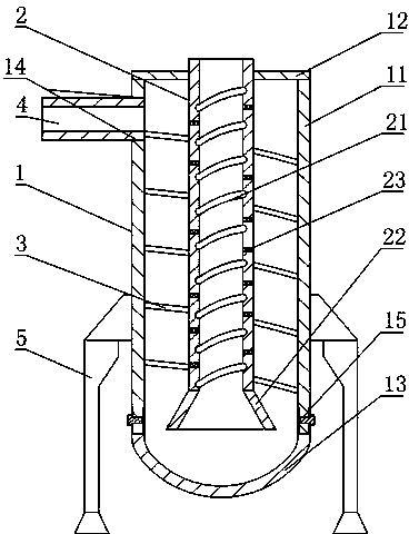
[0015] Such as figure 1 As shown, the airflow drying equipment with a double helix structure includes an outer drying cylinder 1 and an inner drying cylinder 2. The outer drying cylinder 1 includes an outer cylinder body 11 with openings at both ends of the upper and lower ends, and is fixedly connected to the upper end of the outer cylinder body 11 and The top cover 12 that closes the opening of the upper end of the outer cylinder 11, the bottom 13 that is fixedly connected to the lower end of the outer cylinder 11 and closes the opening of the lower end of the outer cylinder 11, and the upper part of the side wall of the outer cylinder 11 is provided with a feed port 14 that penetrates the side wall , the upper and lower ends of the inner drying cylinder 2 are open, the inner drying cylinder 2 is coaxially arranged with the outer cylinder body 11, the lower end opening is arranged in the outer cylinder body 11, the upper end opening passes through the top cover 12, and the ou...

Embodiment 2

[0017] On the basis of Embodiment 1, the present embodiment makes the following further limitations: the lower end of the inner drying cylinder 2 is provided with a conical cylinder 22 with a small upper part and a larger lower part, and the upper end surface of the conical cylinder 22 is connected with the lower end surface of the inner drying cylinder 2. Solid connection.

Embodiment 3

[0019] In this embodiment, the following further limitations are made on the basis of Embodiment 1; the inner drying cylinder 2 is provided with a first heating element 23 in the cylinder wall. In this embodiment, the first heating element 23 can choose to heat a metal wire, a metal rod, or the like.


PUM


Abstract

The invention discloses an air flow drying device with a double helix structure. The air flow drying device comprises an outer drying drum and an inner drying drum. The outer drying drum comprises an outer drum body, a top cover and a drum base, wherein the upper end and the lower end of the outer drum body are provided with openings, the top cover is fixedly connected to the upper end of the outer drum body and seals the opening at the upper end of the outer drum body, and the drum base is fixedly connected to the lower end of the outer drum body and seals the opening at the lower end of the outer drum body. The upper portion of a side wall of the outer drum body is provided with a feeding port penetrating the side wall, the upper end and the lower end of the inner drying drum are provided with openings, the inner drying drum and the outer drum body are coaxial, the opening at the lower end of the inner drying drum is arranged in the outer drum body, the opening at the upper end of the inner drying drum penetrates the top cover, a spiral downward guide plate is arranged in an area between an inner wall of the outer drum body and an outer wall of the inner drying drum, and an inner wall of the inner drying drum is provided with a spiral upward groove. The air flow drying device overcomes the shortcomings of an existing air flow dryer, the height of the device is reduced, the retention time of materials in the dryer is prolonged, and the air flow drying device has the advantages of being good in drying performance, convenient to operate, small in size and low in cost.

Description

technical field [0001] The invention relates to the field of airflow dryers, in particular to airflow drying equipment with a double helix structure. Background technique [0002] The airflow dryer has the advantages of high drying strength, large processing capacity, and simple equipment, and has been widely used in the pharmaceutical, food, and chemical industries. However, the traditional airflow dryer has high equipment, takes up a large space, and the overall structure is not compact, which is easy to cause heat loss, low thermal efficiency, and brings certain difficulties to installation, maintenance, and cleaning. Contents of the invention [0003] The object of the present invention is to overcome the shortcomings of the above-mentioned existing airflow dryers, and provide airflow drying equipment with a double helix structure. [0004] The purpose of the present invention is achieved through the following technical solutions: airflow drying equipment with a d...

Claims


Application Information

Patent Timeline
Patent Type & Authority Applications(China)
IPC IPC(8): F26B17/10F26B25/16F26B25/08
Inventor 王勇
Owner 东莞市国丰粮油有限公司
Learn More