
Adjustable annular flow injection valve and steam injection string

An adjustable and ring-shaped technology, applied in the direction of production fluid, wellbore/well valve device, wellbore/well parts, etc., can solve the problems of fishing failure, complex structure, difficult adjustment of steam injection volume, etc., and achieve easy salvage, The effect of protecting the injection channel and simple structure

Active Publication Date: 2015-01-28
PETROCHINA CO LTD
View PDF8 Cites 3 Cited by
  • Summary
  • Abstract
  • Description
  • Claims
  • Application Information

AI Technical Summary

Problems solved by technology

[0003] In order to overcome the complex structure in the prior art, the difficult adjustment of the steam injection volume during the steam distribution process, the corrosion and scaling phenomenon during the steam injection process, and the self-locking of the steam injection valve and the working cylinder, which easily lead to salvage failure, etc., the present invention provides An adjustable annular flow dispensing valve can solve the problem of adjusting the steam injection volume by replacing the steam injection valve, improve the corrosion and scaling phenomenon during the steam injection process, and avoid the self-locking phenomenon between the steam injection valve and the working cylinder produce

Method used


Image

  • Adjustable annular flow injection valve and steam injection string
  • Adjustable annular flow injection valve and steam injection string
  • Adjustable annular flow injection valve and steam injection string

Examples


Embodiment Construction

[0026] In order to have a clearer understanding of the technical features, purposes and effects of the present invention, the specific implementation manners of the present invention will now be described with reference to the accompanying drawings.

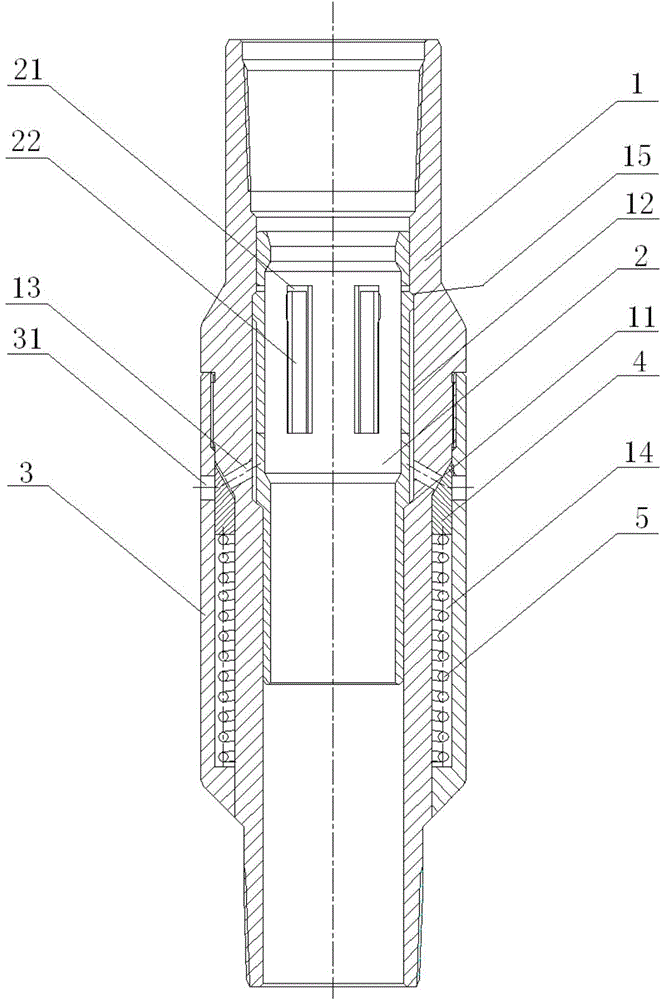
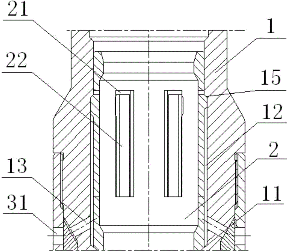
[0027] Such as Figure 1 to Figure 4 As shown, the present invention proposes an adjustable annular flow dispensing valve, which includes a mandrel 1, which has an accommodating chamber 10, and a steam injection valve 2 is arranged in the accommodating chamber 10, and the inner side wall of the mandrel 1 A limit table 11 capable of limiting the steam injection valve 2 is provided, an annular steam injection cavity 12 is formed between the working cylinder 1 and the steam injection valve 2, and the side wall of the steam injection valve 2 is provided with a communicating accommodating cavity 10 and The steam injection through hole 21 of the steam injection chamber 12, the side wall of the work cylinder 1 is provided with a first p...


PUM


Abstract

The invention provides an adjustable annular flow injection valve and a steam injection string. The adjustable annular flow injection valve comprises a working cylinder provided with an accommodating cavity; the accommodating cavity is provided a steam injection valve; the inner side wall of the working cylinder is provided with a limit projection limiting the steam injection valve; an annular steam injection cavity is formed between the working cylinder and the steam injection valve, the side wall of the steam injection valve is provided with steam injection through holes communicating the accommodating cavity and the steam injection cavity, and a first channel communicated with the steam injection cavity is formed on the side wall of the working cylinder; the adjustable annular flow injection valve further comprises a control device to open and close the first channel. The steam injection string comprises the adjustable annular flow injection valves with the heads and tails are connected sequentially in a sealed manner. The adjustable annular flow injection valve is simple in structure, the steam injection quantity can be adjusted during steam configuration, the precipitated dirt is prevented from accumulating, and sands produced by oil wells are prevented from being sucked into the a steam configuration device and are easy to dredge; the steam injection string is capable of injecting steam with different quantities into different steam injecting layers.

Description

technical field [0001] The invention relates to a steam distributing device for steam flooding and steam injection, in particular to an adjustable circular flow distributing valve and a steam injection column. Background technique [0002] Heavy oil steam flooding and steam injection is currently the main technology for heavy oil production. However, due to the different characteristics and classifications of various heavy oil reservoirs, it is necessary to control different steam injection volumes through steam distribution devices in the specific production process. At present, the steam injection valve used in steam flooding and steam injection is mainly in the form of a nozzle. During the construction process, the nozzle and the steam injection valve are lowered into the working cylinder at the same time. The structure is relatively complicated, and the steam injection volume during the steam distribution process is a fixed value. . When it is necessary to adjust the st...

Claims


Application Information

Patent Timeline
Patent Type & Authority Applications(China)
IPC IPC(8): E21B43/24E21B34/06
CPCE21B34/06E21B43/24
Inventor 何传兴张洪宝王巍魏凯戚勇刘祖合赵树杰董奇伟张野
Owner PETROCHINA CO LTD
Learn More