
Automatic discharge method and discharge device of freeze dryer

An automatic discharge device and automatic discharge technology are applied in the direction of conveyor control devices, conveyor objects, transportation and packaging, etc., which can solve problems such as product pollution, burst bottles, equipment damage, etc., to ensure normal operation and improve progress. Bottle speed, the effect of increasing the feeding speed

Active Publication Date: 2016-08-31
ZHEJIANG WHITESON PHARMA
View PDF15 Cites 0 Cited by
  • Summary
  • Abstract
  • Description
  • Claims
  • Application Information

AI Technical Summary

Problems solved by technology

Although the current discharge method can meet a certain degree of process requirements, the transfer monitoring of the discharge link is relatively weak. If a blockage occurs, the control system does not have corresponding automatic processing measures, and it relies heavily on manual intervention. As a result, a series of problems have been brought about; in addition, when the products produced by the automatic feeding and discharging and the freeze dryer are such as 50ml and other large-scale bottle products, blockages are also prone to occur in the area where the freeze dryer shelf is connected to the conveyor belt, but here There are no monitoring or treatment measures in the area, so the vials continue to be pushed out after clogging and squeezed with the feed push rod, resulting in bottle bursting, which brings the risk of product contamination and equipment damage
Therefore, due to the above deficiencies, the discharge speed cannot be set too fast, so as to avoid major failures and fail to improve production efficiency.

Method used


Image

  • Automatic discharge method and discharge device of freeze dryer
  • Automatic discharge method and discharge device of freeze dryer
  • Automatic discharge method and discharge device of freeze dryer

Examples


Embodiment Construction

[0034] The present invention will be further described below in conjunction with the accompanying drawings and specific embodiments.

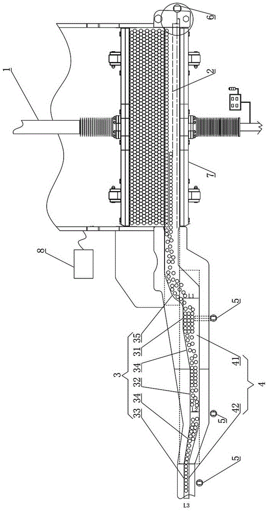
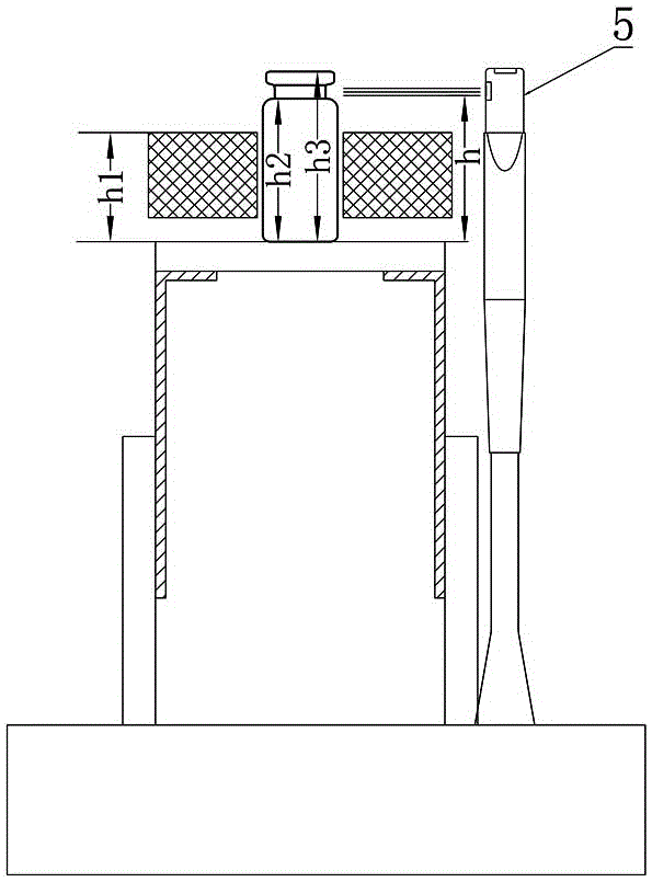
[0035] In the automatic discharge method of the freeze dryer in this embodiment, the discharge device of the freeze dryer includes a discharge transmission channel that is docked with the freeze dryer to transport bottles, and the discharge transmission channel includes a conveyor belt assembly for arranging multiple rows of bottles into a single row 4. The conveyor belt assembly 4 includes a plurality of independent conveyor belts, and the plurality of independent conveyor belts are sequentially connected along the discharge direction. The method includes the following steps:

[0036] 1) Start discharging, and push out multiple rows of vials from the freeze dryer to the conveyor belt of conveyor belt assembly 4, and the vials on the conveyor belt are conveyed from multiple rows to the last single row;

[0037] 2) In step 1), if there is a bott...


PUM


Abstract

The invention discloses an automatic discharging method for a freeze dryer. The automatic discharging method comprises the following steps: carrying out bottle blockage monitoring on conveyer belts on a discharging conveyer channel, and controlling the rotation directions of the conveyer belts with bottle blockage to dredge the bottle blockage. The invention also discloses an automatic discharging device for the freeze dryer. The automatic discharging device comprises a discharging conveyer channel, wherein the discharging conveyer channel comprises a conveyer belt assembly which is used for arranging a plurality of lines of bottles into a single line; the conveyer belt assembly comprises a plurality of independent conveyer belts which are butted in sequence along the discharging direction; a first bottle body detection member is arranged on the conveyer belt assembly and used for detecting whether the conveyer belts have bottle blockage or not and sending detection signals to a control assembly; the control assembly is used for switching the rotation directions of corresponding conveyer belts according to the detection signals so as to dredge blocked bottles. Both the method and the device disclosed by the invention have the advantages of being simple to operate, rapid in feeding speed, and capable of full-automatically monitoring the bottle blockage and automatically and rapidly dredging the bottle blockage.

Description

technical field [0001] The invention mainly relates to the technical field of freeze-drying machines, in particular to an automatic discharging method and a discharging device of a freeze-drying line. Background technique [0002] The automatic loading and unloading of the freeze dryer passes the semi-stoppered vials through the feeding integration device and bottle unscrambling device, and sends them to the shelf of the freeze dryer combined with the feeding push rod. After completing the freeze-drying process cycle, it is combined by the discharge push rod The integrated discharge device sends the vials out of the shelf, and transfers them to the capping machine and subsequent processes. The entire feeding and discharging process is completely controlled by the control system without manual intervention, avoiding manual contact with the product, thereby preventing the transfer process of the product to the greatest extent. The pollution caused in the environment, so the us...

Claims


Application Information

Patent Timeline
Patent Type & Authority Patents(China)
IPC IPC(8): B65G47/14B65G43/08
Inventor 陈双好王海鸥谭亮钟元龙
Owner ZHEJIANG WHITESON PHARMA
Learn More