
Rear plug type case installation rack

A plug-in and mounting frame technology, which is applied in the direction of support structure installation, casing/cabinet/drawer parts, clamping/drawing device, etc., can solve the loss of cooling capacity along the way, heavy weight, and chassis mounting frame Large volume and other problems, to reduce the loss along the way, reduce the overall size and materials, and solve the effect of large volume

Active Publication Date: 2015-01-21
CHINA AVIATION OPTICAL-ELECTRICAL TECH CO LTD
View PDF8 Cites 13 Cited by
  • Summary
  • Abstract
  • Description
  • Claims
  • Application Information

AI Technical Summary

Problems solved by technology

[0004] The purpose of the present invention is to provide a rear plug-in chassis mounting frame to solve the problems of large volume, heavy weight and large cooling loss along the existing chassis mounting frame

Method used


Image

  • Rear plug type case installation rack
  • Rear plug type case installation rack
  • Rear plug type case installation rack

Examples


Embodiment Construction

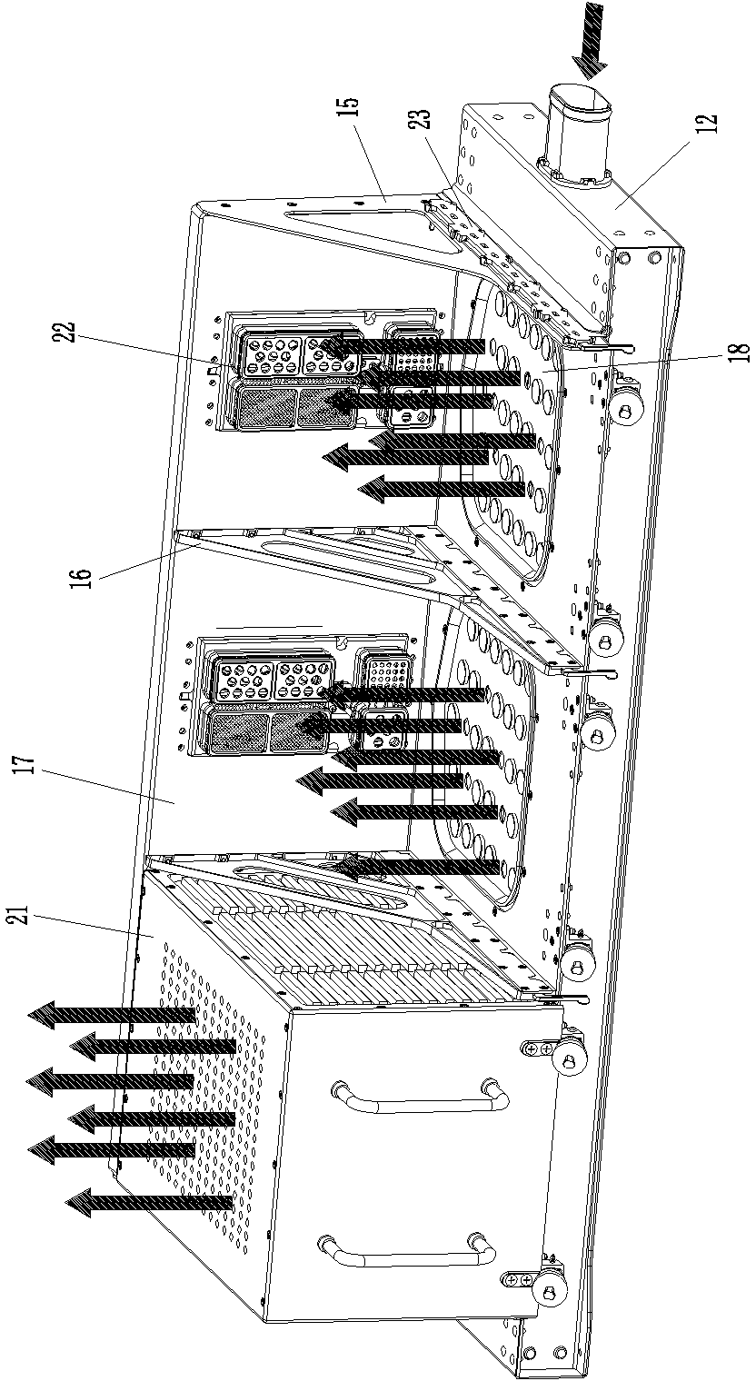
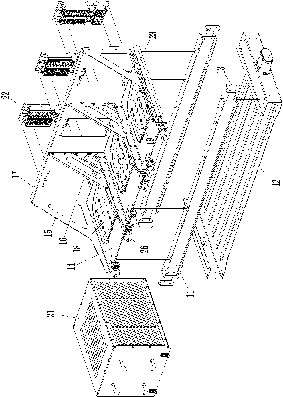
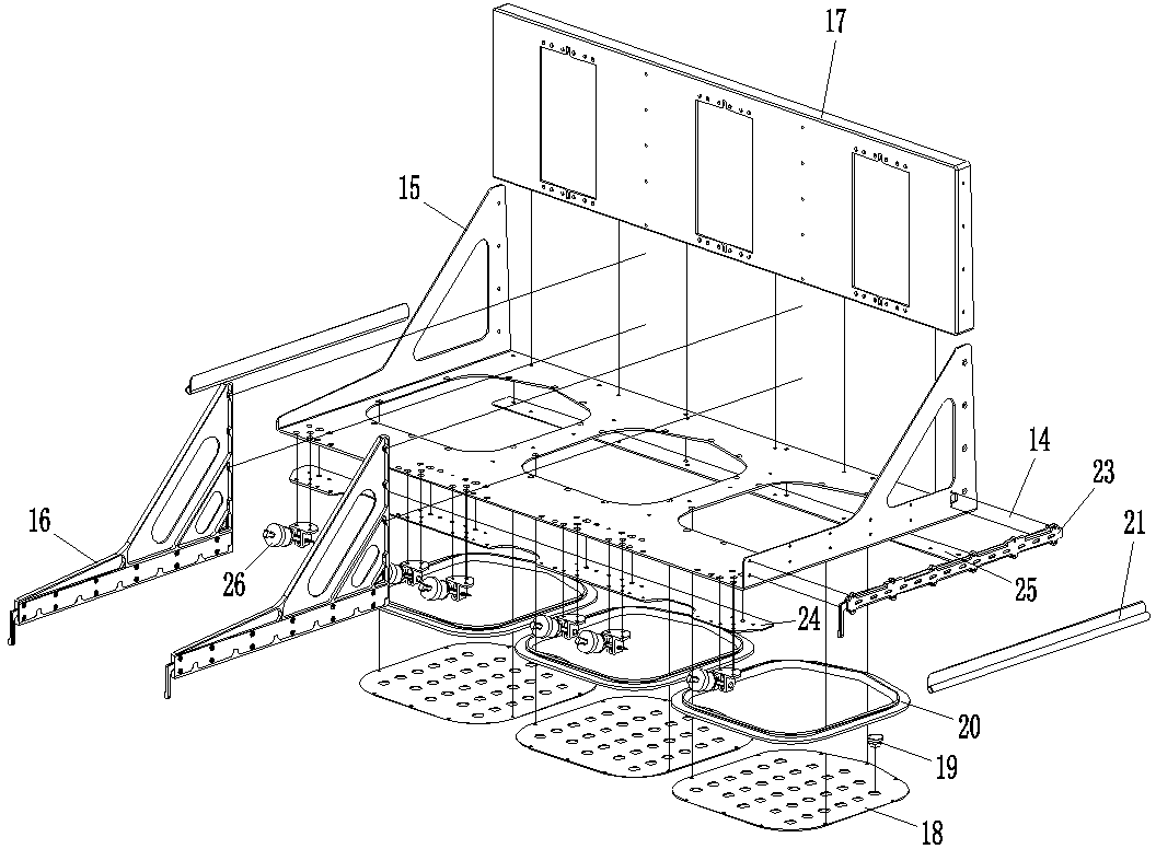
[0015] Examples of rear-swappable chassis mounts, such as Figure 1-3 As shown, the rear plug-in chassis mounting bracket includes a support seat, a guide piece, and a front tightening device.

[0016] The supporting seat includes a load-bearing frame 11 and an air channel plate 12 arranged on the load-bearing frame. The load-bearing frame 11 and the air channel plate 12 together form an air channel structure. Specifically, there are two beams and they are arranged in parallel. The air channel plate 12 includes a substantially U-shaped bottom plate located at the lower part. At the same time, the surrounding wall on the corresponding side of the air duct is formed, so that the load-bearing frame 11 and the air duct plate 12 together form a groove structure with only an upper side opening. In this embodiment, three chassis installation positions are arranged side by side along the left and right directions on the supporting seat with the above structure. Of course, in other em...


PUM


Abstract

The invention relates to the field of electrical equipment, in particular to a rear plug type case installation rack. The rear plug type case installation rack comprises supporting bases, a guiding element is arranged on each supporting base, two or more case installation positions are arranged on each supporting base side by side in a left and right mode, each supporting base comprises a bearing frame and an air duct plate arranged on the corresponding bearing frame, an air duct is formed by each air duct plate and the corresponding guiding element in an enclosed mode, and the portions, corresponding to the case installation positions, of the matched position of each guiding element and the corresponding air duct plate are provided with through air duct openings. The rear plug type case installation rack solves the problems that an existing case installation rack is large in size, high in weight and large in cooling capacity linear loss.

Description

technical field [0001] The invention relates to the field of electrical equipment, in particular to a rear plug-in type chassis installation frame. Background technique [0002] With the continuous development of equipment in the electrical field, the miniaturized functional module chassis has been more and more widely popularized. The supporting facilities of the functional module chassis are the chassis mounting frame, one of the rear side of the chassis and the rear side of the chassis mounting frame There is an electrical connector plug on one, and an electrical connector socket on the other; in addition, the chassis mounting frame is also provided with guide rails that cooperate with the front and rear guides of the chassis. When using, you only need to push the chassis from front to back along the corresponding guide rails. Inserting, prompting the electrical connector plug to be mated with the socket can activate the corresponding function of the chassis. Since the ...

Claims


Application Information

Patent Timeline
IPC IPC(8): H05K5/00H05K5/02H05K7/20
CPCH05K7/1412H05K7/20563
Inventor 杨成博陈建超吕云朋周卫可
Owner CHINA AVIATION OPTICAL-ELECTRICAL TECH CO LTD
Learn More