Method for manufacturing variable-pitch optical grating

A variable pitch grating and manufacturing method technology, applied in the field of spectroscopy, can solve problems such as the collapse of photoresist grooves, the impact of grating technical indicators, and difficult control of process conditions, achieving low cost, controllable process, and shortened production cycle Effect

Inactive Publication Date: 2015-01-21
CHANGCHUN INST OF OPTICS FINE MECHANICS & PHYSICS CHINESE ACAD OF SCI
View PDF6 Cites 7 Cited by
  • Summary
  • Abstract
  • Description
  • Claims
  • Application Information

AI Technical Summary

Problems solved by technology

[0005] In order to solve the problems that the existing method adopts hot melting, the process conditions are difficult to control, it is easy to cause the collapse of the photoresist groove, and have a great impact on the technical indicators of the grating, and the present invention provides a method for manufacturing a variable pitch grating.

Method used


Image

  • Method for manufacturing variable-pitch optical grating
  • Method for manufacturing variable-pitch optical grating

Examples


specific Embodiment approach 1

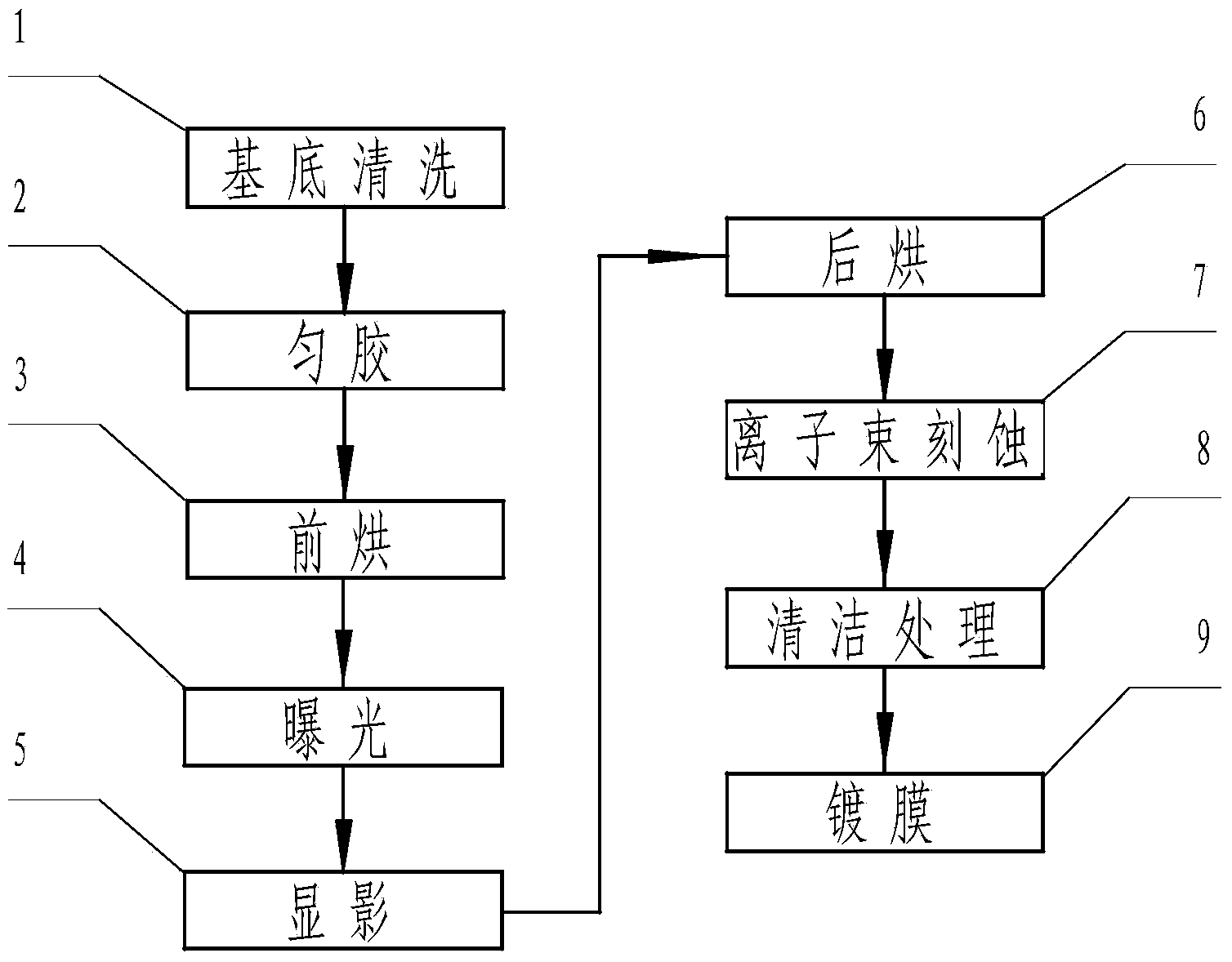
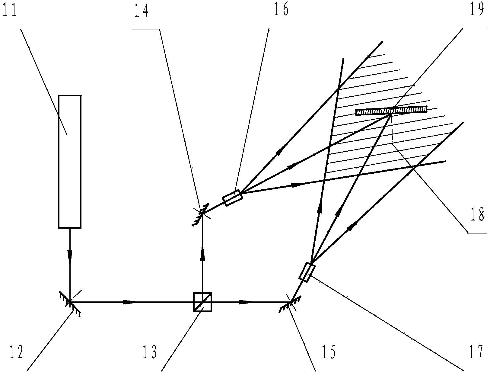
[0014] Specific implementation mode 1. Combination figure 1 with figure 2 Illustrate the present embodiment, the manufacture method of variable pitch grating, this method is realized by the following steps:

[0015] Substrate cleaning 1: The grating substrate should be single crystal silicon with no bubbles, no scratches, and polished, and clean the grating substrate with a cleaning solution such as acetone to ensure that the surface of the substrate is clean, dense and dry, so as to facilitate the contact between the photoresist and the surface of the substrate. Adhesion.

[0016] Coating 2: Apply photoresist on the cleaned grating substrate, and use the rotation method to uniform the coating, that is, drop the photoresist on the grating substrate, and obtain a uniform photoresist film by centrifugal rotation. The thickness of the glue layer is mainly controlled by the rotation speed during glue spreading, the higher the speed is, the thinner the glue layer is, and the low...

specific Embodiment approach 2

[0025] Specific embodiment two, combine figure 1 with figure 2 Describe this implementation mode, this implementation mode is an embodiment of the manufacturing method of the variable pitch grating described in the first specific implementation mode:

[0026] 1. Clean the polished monocrystalline silicon substrate without bubbles and scratches with a cleaning solution such as acetone;

[0027] 2. Coating photoresist on the monocrystalline silicon substrate, the photoresist is Shiply1805 positive photoresist, the rotation speed is controlled at 1700-5000 rpm during coating, and the coating time is not less than 30 seconds. This can ensure the full volatilization of the solvent and the uniformity of the thickness of the film. The thickness of the coating is 300-700nm.

[0028] 3. Put the photoresist-coated grating substrate into the oven for pre-baking, raise the temperature of the oven to 90°C, and take it out after 30 minutes;

[0029] 4. Expose the grating substrate in th...


PUM


Abstract

The invention discloses a method for manufacturing a variable-pitch optical grating and relates to the technical field of spectrums. The method for manufacturing the variable-pitch optical grating solves the problems that according to an existing method adopting hot melting, the technological conditions are hard to control, collapse of a photoresist etching groove is caused easily, and the technical indexes of an optical grating are affected seriously. The method for manufacturing the variable-pitch optical grating comprises the steps of washing of a substrate, photoresist evening, prebaking, exposure, developing, postbaking, ion beam etching, cleaning and film coating. According to the technological process for manufacturing the variable-pitch optical grating, cost is low, the method is easy to implement, cost is reduced greatly, and the manufacturing cycle is shortened. Due to the fact that the variable-pitch optical grating has the increasingly outstanding unique advantages of aberration correction, high resolution and flat focus field, the variable-pitch optical grating is widely applied in the fields such as the spatial spectrograph field, the plasma diagnosis field, the synchrotron radiation monochrometer field and the optical fiber communication field.

Description

technical field [0001] The invention relates to the field of spectrum technology, in particular to a manufacturing process method of a variable pitch grating. Background technique [0002] Traditional diffraction gratings are equal-pitch gratings, which are the core components of various spectroscopic instruments. However, with the advancement of science and technology, the unique advantages of variable pitch gratings such as aberration correction, high resolution, and flat focal field have become increasingly prominent, making them widely used in space spectrometers, plasma diagnostics, synchrotron radiation monochromators, and optical fiber communications. Widely used in other fields. Variable pitch gratings with aberration correction, high resolution can be obtained under grazing incidence conditions, this feature will be further developed and utilized in monochromators and spectrometers, which is important for soft X-rays and extreme ultraviolet radiation significance....

Claims


Application Information

Patent Timeline
Patent Type & Authority Applications(China)
IPC IPC(8): G02B5/18
CPCG02B5/1861G02B5/1847G02B5/1857
Inventor 李文昊姜岩秀巴音贺希格杨硕赵旭龙吴娜
Owner CHANGCHUN INST OF OPTICS FINE MECHANICS & PHYSICS CHINESE ACAD OF SCI
Why Eureka
Try Eureka