Connecting clamp for template splicing

A formwork assembly and clamping technology, which is applied in the direction of formwork/formwork/work frame connectors, connecting components, mold auxiliary parts, etc., can solve the problems of easy damage, slow construction speed, looseness, etc., and achieve simple connection, The effect of firm connection and tight connection

Active Publication Date: 2015-01-21
GUANGZHOU YIDA MACHINERY
View PDF12 Cites 6 Cited by
  • Summary
  • Abstract
  • Description
  • Claims
  • Application Information

AI Technical Summary

Problems solved by technology

[0002] In the prior art, when building formwork, steel formwork or wooden formwork is assembled and connected, most of them use ordinary bolts and nuts to perforate the assembled connection. This traditional connection device has obvious shortcomings: slow construction speed, formwork The quality of assembly is not easy to guarantee, it is easy to be damaged at the construction site, and it is easy to loosen by itself after the earthquake, which sometimes seriously affects the quality of concrete pouring: there are also many companies that use the assembly card disclosed in Chinese patent ZL99205850·3, its structure is : There are double hook feet on the main part, and there are fastening bolts with saddle-shaped plates opposite to the double hook feet. When in use, there must be matching double holes on the frame of the formwork. Ride on the top of the frame of the two templates, and then tighten the jacking bolts. The biggest advantage of this type of connecting device is that the construction speed is fast, but there are still obvious shortcomings: the frame of the template must have standard double holes. The site is also easy to be damaged, and it is easy to loosen by itself after being shaken. At the same time, the internal size of the double hook feet is strictly required. After repeated use, both the matching double holes of the formwork frame and the double hook feet themselves will have dimensional deviation due to wear and tear. It will inevitably affect the quality of formwork assembly, thereby affecting the quality of concrete pouring; another example: the fixture scheme disclosed in Chinese patent ZL01271107.1 consists of three parts: a wedge with wedge teeth, and a left half clamp with a rack piece and the right half piece, when in use, the left and right half pieces are aligned on the frame of the template, at this time, the rack on the left half piece passes through the groove of the right half piece, and then the wedge The body is inserted from the longitudinal hole of the groove and meshed with the horizontal rack. When the wedge force is applied, due to the function of the helical teeth, the wedge teeth and the rack are engaged in a lateral displacement, thereby driving the two halves of the clips to tighten each other. Combined together; the biggest advantage of this kind of fixture is that the speed of the work is fast, the formwork is assembled and fastened reliably, and there is no need to punch holes on the frame of the formwork, but there are high costs and other unsatisfactory features: Another example is Chinese patent ZL03137432·8 The disclosed new connector is mainly composed of a special-shaped plate bolt and a matching T-shaped spring wedge. And it is stuck on the inner surface of the bolt head. After the wedge is tightened, the wedge body produces a certain elastic bending. Its biggest advantages are simple structure, convenient construction, wear resistance and collision resistance, and long service life. The disadvantage is that the wedge The elastic bending of the body is prone to fatigue, and the artificial wedging force is not easy to grasp. When using it, the perforation and fastening one by one still affects the construction speed, and it is also prone to loss, etc.

Method used


Image

  • Connecting clamp for template splicing
  • Connecting clamp for template splicing
  • Connecting clamp for template splicing

Examples


Embodiment Construction

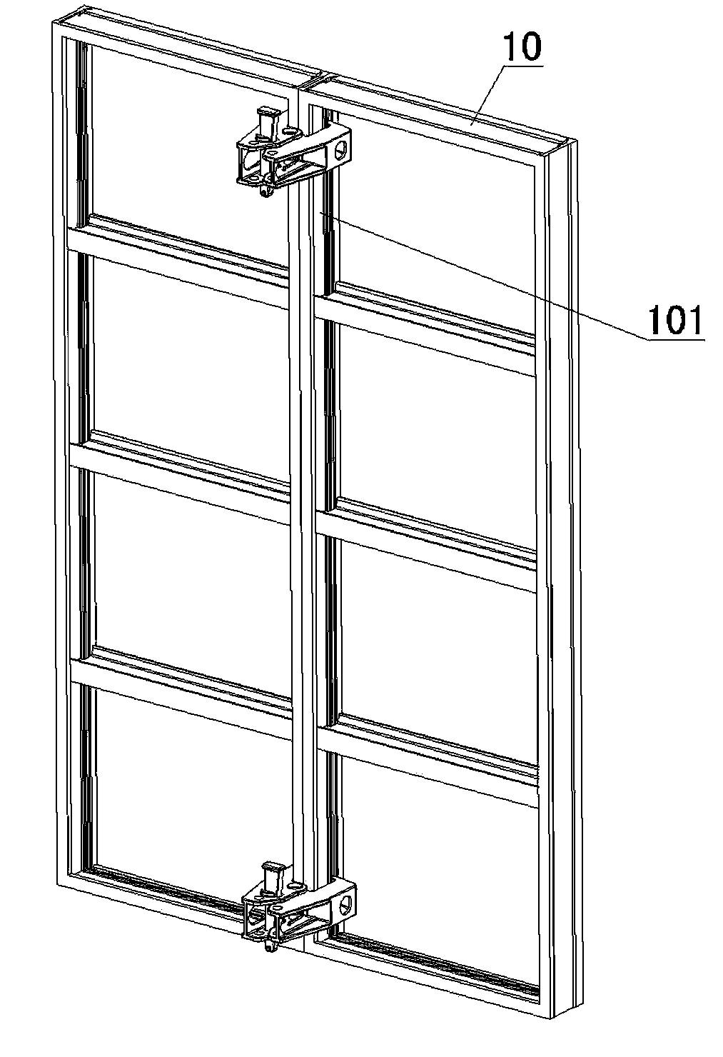
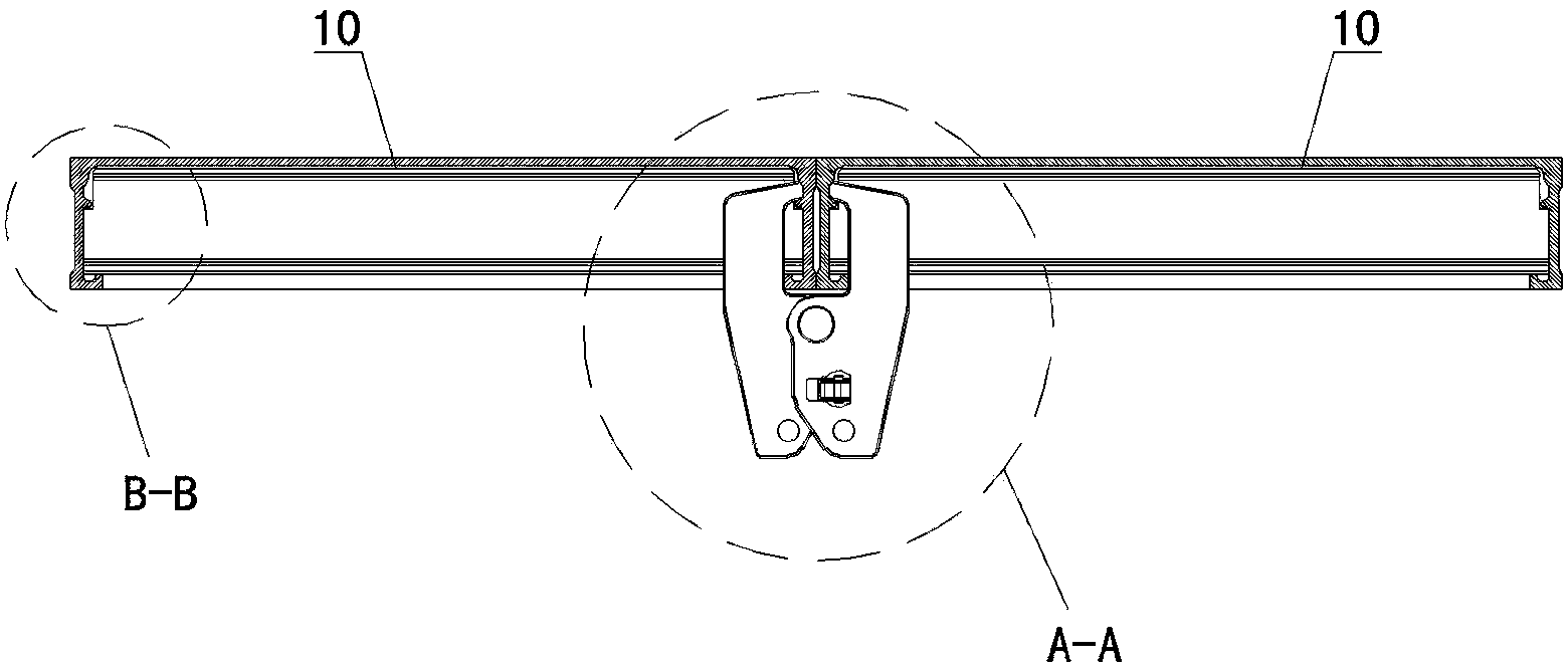
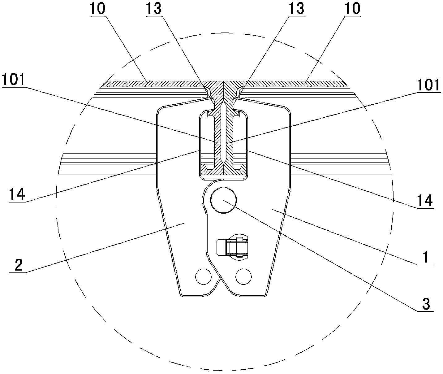
[0025] Such as Figure 1-Figure 11 As shown, the connecting jig for template assembly according to the present invention includes a left clip 1 and a right clip 2, and the left clip 1 and the right clip 2 are rotatably connected together through a rotating shaft 3, and the left The front chuck parts of the clip 1 and the right clip 2 have a clamping surface 13 and a positioning and alignment surface 14 corresponding to the frame 101 of the template 10, and the rear parts of the left clip 1 and the right clip 2 are provided with The front clamp parts of the left clip 1 and the right clip 2 can form a locking device for clamping the frames 101 of two adjacent templates 10 . In order to make the structure of the present invention various, it is possible that the locking device includes a perforation 11 arranged at the rear of the left clip 1, and an oblique wedge 4 that can move up and down and is inserted in the perforation 11, wherein the One side of the oblique wedge 4 corres...


PUM


Abstract

A connecting clamp for template splicing comprises a left toggle clip and a right toggle clip, wherein the left toggle clip and the right toggle clip are rotatably connected together through a rotary shaft, the chuck position of the front end of the left toggle clip and the chuck position of the front end of the right toggle clip are provided with clamping faces and positioning and leveling faces matched with and corresponding to frames of templates, and clamping devices enabling the chuck position of the front end of the left toggle clip and the chuck position of the front end of the right toggle clip to form frames clamping two adjacent templates are arranged at the rear portion of the left toggle clip and at the rear portion of the right toggle clip. The connecting clamp for template splicing has the advantages that the connecting clamp is simple in structure, convenient to use, low in cost and long in service life and is not easily damaged and lost, the frames of the templates are not needed to be punched, the templates can be automatically positioned and leveled in the wedge block fastening process and are reliable in splicing and fastening and high in quality, and the connecting clamp can be suitable for splicing of various types of templates.

Description

technical field [0001] The invention belongs to the field of building formwork connecting devices, and relates to a connecting jig for formwork assembly. Background technique [0002] In the prior art, when building formwork, steel formwork or wooden formwork is assembled and connected, most of them use ordinary bolts and nuts to perforate the assembled connection. This traditional connection device has obvious shortcomings: slow construction speed, formwork The quality of assembly is not easy to guarantee, it is easy to be damaged at the construction site, and it is easy to loosen by itself after the earthquake, which sometimes seriously affects the quality of concrete pouring: there are also many companies that use the assembly card disclosed in Chinese patent ZL99205850·3, its structure is : There are double hook feet on the main part, and there are fastening bolts with saddle-shaped plates opposite to the double hook feet. When in use, there must be matching double holes...

Claims


Application Information

Patent Timeline
Patent Type & Authority Applications(China)
IPC IPC(8): E04G17/07
CPCE04G11/06E04G11/10E04G17/04E04G17/042E04G17/045F16B2/14B28B7/0014E04G17/0735E04G17/0757
Inventor 刘成文
Owner GUANGZHOU YIDA MACHINERY
Why Eureka
Try Eureka