Kiln feeding system for directly injecting refuse-derived fuel into cement kiln

A technology for waste fuel and cement kiln, which is applied in the field of kiln entry system that directly injects waste fuel into cement kiln, can solve the problems of long conveying stroke and no-load return journey, large area and high cost, so as to improve the conveying capacity and reduce the cost. The effect of manufacturing cost and footprint reduction

Active Publication Date: 2015-01-14
BEIJING BUILDING MATERIALS ACADEMY OF SCI RES +1
View PDF6 Cites 2 Cited by
  • Summary
  • Abstract
  • Description
  • Claims
  • Application Information

AI Technical Summary

Problems solved by technology

Since it is very expensive to build a high-altitude silo, at least 1 million yuan is required, and the project covers a large area, at least 100 square meters
Since the grab equipment is a non-continuous conveying equipment, and the conveying stroke and the empty return journey are very long, the conveying capacity of the grab equipment is greatly reduced, and it is difficult to ensure the normal supply of materials to the high silo, which greatly restricts the treatment of waste fuel. scale
According to the conventional method, if the garbage fuel is directly transported to the feed port of the calciner with a length of more than 40 meters through the conveyor belt, although the continuous delivery of the garbage fuel can be guaranteed, the project will occupy a larger area, at least 500 square meters , from an economic point of view it is not worth the loss
If the garbage fuel is directly transported to the feed port of the decomposition furnace with a height of more than 40 meters through the bucket elevator, although the project footprint can be greatly reduced, the continuous delivery of garbage fuel cannot be realized

Method used


Image

  • Kiln feeding system for directly injecting refuse-derived fuel into cement kiln
  • Kiln feeding system for directly injecting refuse-derived fuel into cement kiln
  • Kiln feeding system for directly injecting refuse-derived fuel into cement kiln

Examples


Embodiment Construction

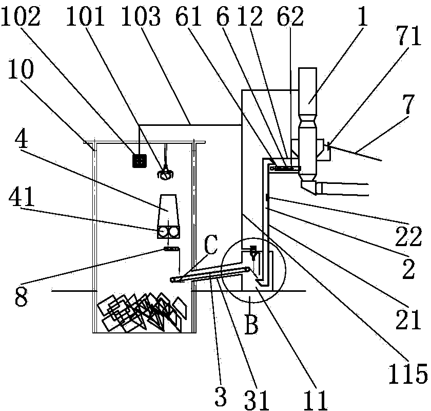
[0034] Such as Figure 1 to Figure 9 As shown, this embodiment provides a kiln entry system for directly injecting garbage fuel into a cement kiln. The system includes a pyrolysis furnace 1 with a feed inlet located at a high place, and the feed inlet is upward. The system also includes garbage fuel. Vertical continuous hoist 2, garbage fuel horizontal continuous conveyor 3 and garbage fuel buffer bin 4; the garbage fuel vertical continuous hoist 2 is adjacent to and juxtaposed with the pyrolysis furnace 1, and the garbage fuel One side of the upper end of the vertical continuous hoist 2 is provided with a discharge port, the discharge port faces downward and is positioned above the feed port of the pyrolysis furnace 1, and the other side of the lower end of the vertical continuous hoist 2 for waste fuel is There is a feed port on the side, the feed port faces upwards, from figure 1 and Figure 9 It can be seen from the figure that the discharge port at the upper end of the ...


PUM


Abstract

The invention discloses a kiln feeding system for directly injecting refuse-derived fuel into a cement kiln. The kiln feeding system comprises a pyrolyzing furnace with a high-position feeding port, a vertical continuous hoist, a horizontal continuous conveyor and a buffer bin, the vertical continuous hoist and the pyrolyzing furnace are adjacent to each other and are arranged side by side, a discharging port is formed in one upper side of the vertical continuous hoist and positioned above the feeding port of the pyrolyzing furnace, a feeding port is formed in the other side of the lower end of the vertical continuous hoist, a discharging port is formed in one end of the horizontal continuous conveyor and positioned above the feeding port of the vertical continuous hoist, a feeding port is formed in the other end of the horizontal continuous conveyor, the buffer bin is arranged above the feeding port of the horizontal continuous conveyor, and a feeding device is arranged at the bottom of the buffer bin. The kiln feeding system for directly injecting the refuse-derived fuel into the cement kiln is capable of improving conveying capacity of refuse-derived fuel greatly, and the occupied area of the kiln feeding system can be decreased greatly.

Description

technical field [0001] The invention relates to a system for injecting fuel into a cement kiln, in particular to a kiln inlet system for directly injecting waste fuel into a cement kiln. Background technique [0002] Disposal of waste in the cement industry has become an inevitable trend for the sustainable development of the cement industry. With the acceleration of urbanization, the siege of garbage has plagued urban management. The development of cement kiln alternative fuel technology has been maturely applied in foreign developed countries for nearly 30 years, and its disposal safety has been recognized by the Basel Convention. From the perspective of the physical form of alternative fuels, there are three ways for cement kilns to use alternative fuels, namely solid, liquid and gas. In developed countries, waste sorting is more developed, mainly industrial waste and RDF (refuse derived fuel), which are basically crushed and sent directly into the kiln as solid fuel, m...

Claims


Application Information

Patent Timeline
Patent Type & Authority Applications(China)
IPC IPC(8): F23G5/44F23K3/00
CPCF23G5/444F23G2205/00
Inventor 刘海兵李威顾军陈晓东蔡文涛郝利炜王肇嘉
Owner BEIJING BUILDING MATERIALS ACADEMY OF SCI RES
Why Eureka
Try Eureka